
Midterm
Process
I started thinking about my physical computation midterm way before —probably even longer than a month. Unfortunately, I'm only getting to the midterm documentation now.
I met with Tom during office hours on September 18th to discuss my first idea. The first idea I had was to create a Pepper's Ghost illusion and use an Arduino OLED screen to display a p5.js sketch that reacts to an ultrasonic sensor. The animation would be of a person running, and as you get closer, the person runs faster, and after a certain distance, the sketch says "Boo!" Tom pointed out that the interaction is minimal, and every day, it is essentially just walking back and forth.
Then I started thinking of another midterm idea based on an article I came across: https://www.nationalgeographic.com/animals/article/fireflies-light-pollution-green-spaces-new-york-dc. I wanted to make an installation based on this article. But the challenge was that I didn't want to use LEDs to represent fireflies. This idea was definitely one that I pursued for a bit because it was exciting to me.
On September 24th, I asked Arjun if we wanted to work with me for the midterm. He already had a line of enquiry, he wanted to pursue, but he did want to contribute to as many projects as he could, so later that week on October 1st, we discussed my idea a little bit more, he helped me think it through a bit more in terms how I might want to approach it, and also got me thinking more into about the project and. I realized that I wanted to represent 'resilience' through fireflies rather than just an installation.
Then I spoke with Christina Tang on Friday, October 3rd, and she told me that LEDs and a form of shadow from a good light source would be a good approach for the Week 5 lab, using a bulb to get myself more familiar with LEDs.


Then later on the 4th, I went to Princeton to visit one of my friends, and they told me that this project might seem really interesting to me, but as a viewer, it could be brushed off and doesn't necessarily engage. So I thought more about my project that day and came up with the idea of my board game, 'Trash!'.
Initially, Matt helped me come up with the idea that I'd have a big bin and people would use tokens from that bin to sort trash into multiple bins. So on the 5th, I prototyped with cardboard and conductive tape, using resistors. With different resistor values, the speaker would be triggered.


#include "pitches.h";
int peakValue = 0;
int threshold_1 = 750;
int threshold_2 = 820;
int note[] = {
NOTE_A4, NOTE_G4};

const int speakerPin = 8;      // pin number for the speaker
const int noteDuration = 200;   // play notes for 20 ms
void setup() {
  // put your setup code here, to run once:
  Serial.begin(9600);
}

void loop() {
  // Serial.println(analogRead(A1));
  int sensorValue = analogRead(A1);
  // map the results from the sensor reading's range
  // to the desired pitch range:
  // check if it's higher than the current peak:
  if (sensorValue > peakValue) {
    peakValue = sensorValue;
  }
  if (sensorValue <= threshold_1) {
    if (peakValue > threshold_1 && peakValue < threshold_2) {
      // you have a peak value:
      tone(speakerPin, note[0], noteDuration);
      // delay as long as the note is playing:
      delay(noteDuration);
      // reset the peak variable:
      peakValue = 0;
    } else if (peakValue > threshold_2) {
      tone(speakerPin, note[1], noteDuration);
      // delay as long as the note is playing:
      delay(noteDuration);
      // reset the peak variable:
      peakValue = 0;
    }
}
}
Then, in the next class, we discussed our projects, and after that, I realized I hadn't thoroughly thought through the project's concept. And the way I presented was confusing because I get nervous during presentations, so people in the class thought I was trying to make an actual trash segregator, not the board game. Then Tom suggested that I collaborate with Galt and use computer vision, but then I clarified that I wanted to make a board game. But, for a moment, I thought it would be really interesting to work on building an actual trash segregator. However, I didn't want to use computer vision because, to me, it didn't make sense: using a tool that generates trash to create a tool to segregate waste. So the same week, I met with Tom again.
After meeting with Tom, he agreed with me that the computer sensors aren't necessarily the best way to detect trash, and he suggested that if I'm really interested, I could look into this for my thesis. He suggested that I use Light and Color sensors, try it out from the Shop on the floor, and also use p5.js for the game's audio output.
Then I met with Phil, and he gave me ideas for fabricating. He told me to use makercase to make a box, and since I know a little bit of Rhino, he said I could potentially design a trash chute. He said that I should use Fusion 360 for it. He also suggested that I get plywood to fabricate from Home Depot or Lowe's and get about a quarter-inch-thick wood.

After that, I asked Phil if there were color and light sensors available in the ER, but he said there weren't, so I emailed Tom to ask what resources I could use to find them. But the next day, I was near the shop. I was talking to Prisha, who told me to try working with RFID or hall-effect sensors, and she also told me to prototype my midterm. She said the light sensor is most likely available in the Shop, so I went with her to the shop and got the color sensor.
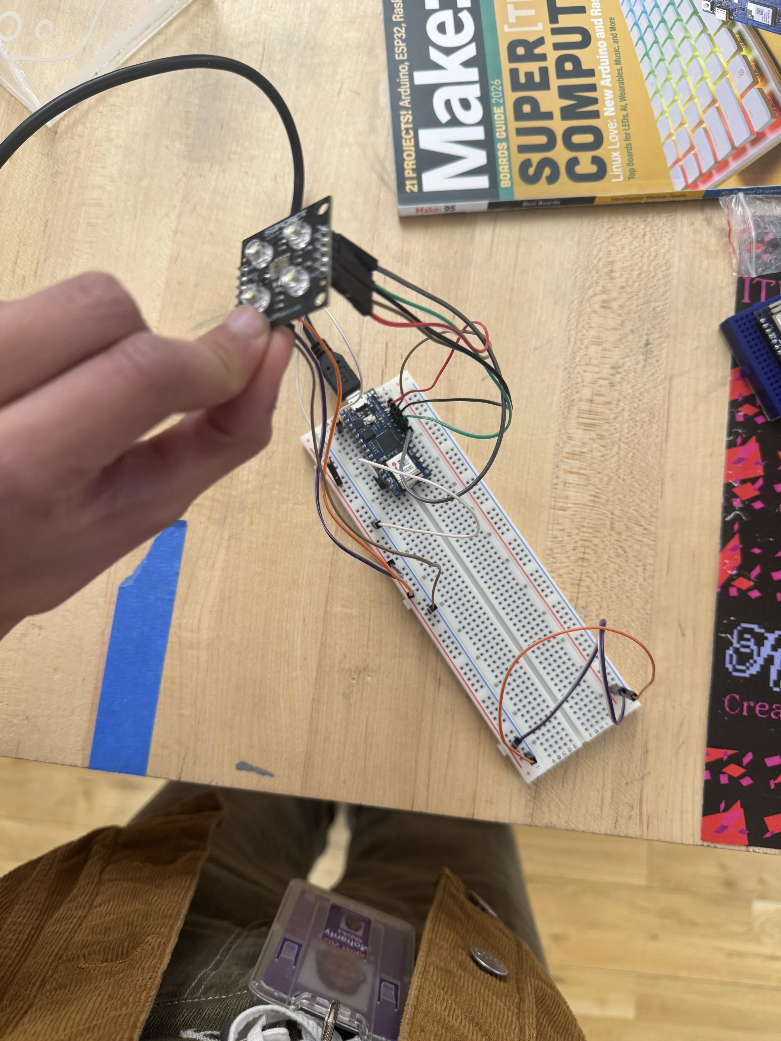
Then, after that, for the next couple of days, I spent some time looking into the datasheet: https://cdn-learn.adafruit.com/downloads/pdf/adafruit-as7341-10-channel-light-color-sensor-breakout.pdf, then, while looking online, I also came across this GitHub page: https://github.com/samthetinkerer/DIY_Light-spectrum-analyser. To start off testing the sensor, I used this code as a reference and updated it. During that time, I was thinking about using the TCA9548A multiplexer because, as per my initial plan, I wanted to connect three of the sensors. At this point, I still hadn't clearly figured out the configuration of a sensor for color detection. While testing the initial code, I saw orange as the highest value at some points, but I couldn't figure out why, so I emailed Tom.
// code adapted from samthetinkerer DIY_Light-spectrum-analyser


/* This example will read all channels from the AS7341 and print out reported values */

#include <Adafruit_AS7341.h>
#include <Arduino.h>
#include <Wire.h>

Adafruit_AS7341 as7341;

int violet  = 0;
int blue  = 0;
int teal  = 0;
int green = 0;
int yellow = 0;
int Yellowgreen = 0;
int orange = 0;
int red = 0;
int farRed = 0;
void setup() {
  Serial.begin(115200);

  // Wait for communication with the host computer serial monitor
  while (!Serial) {
    delay(1);
  }

  if (!as7341.begin()){
    Serial.println("Could not find AS7341");
    while (1) { delay(10); }
  }

  as7341.setATIME(100);
  as7341.setASTEP(999);
  as7341.setGain(AS7341_GAIN_256X);
}

void loop() {
  // Read all channels at the same time and store in as7341 object
  if (!as7341.readAllChannels()){
    Serial.println("Error reading all channels!");
    return;
  }

  violet  = map(as7341.getChannel(AS7341_CHANNEL_415nm_F1),0.0,65536.0,0.0,400.0);
  blue  = map(as7341.getChannel(AS7341_CHANNEL_445nm_F2),0.0,65536.0,0.0,400.0);
  teal  = map(as7341.getChannel(AS7341_CHANNEL_480nm_F3),0.0,65536.0,0.0,400.0);
  green = map(as7341.getChannel(AS7341_CHANNEL_515nm_F4), 0.0, 65536.0, 0.0, 400.0);
  yellow = map(as7341.getChannel(AS7341_CHANNEL_555nm_F5), 0.0, 65536.0, 0.0, 400.0);
  Yellowgreen = map(as7341.getChannel(AS7341_CHANNEL_590nm_F6), 0.0, 65536.0, 0.0, 400.0);
  orange = map(as7341.getChannel(AS7341_CHANNEL_630nm_F7), 0.0, 65536.0, 0.0, 400.0);
  red = map(as7341.getChannel(AS7341_CHANNEL_680nm_F8), 0.0, 65536.0, 0.0, 400.0);
  farRed = map(as7341.getChannel(AS7341_CHANNEL_NIR), 0.0, 65536.0, 0.0, 400.0);

  Serial.print("violet: ");
  Serial.println(violet);
  Serial.print("blue: ");
  Serial.println(blue);
  Serial.print("teal: ");
  Serial.println(teal);
  Serial.print("green: ");
  Serial.println(green);
  Serial.print("yellow: ");
  Serial.println(yellow);
  Serial.print("Yellowgreen: ");
  Serial.println(Yellowgreen);
  Serial.print("orange: ");
  Serial.println(orange);
  Serial.print("red: ");
  Serial.println(red);
  Serial.print("farRed: ");
  Serial.println(farRed);
}
After I emailed Tom to ask whether I needed a multiplexor, and he told me that, rather than using a multiplexor or multiple controllers, I should try working with just one. And in retrospect, I do agree: it was a better strategy to get one working with one bin, get the sending to work reliably, and connect it via asynchronous serial to p5.js.
He mentioned that if this project is interesting, I should spend the extra money on additional hardware for the final.
Tom sent me his notes on the sensor: https://tigoe.github.io/LightProjects/spectrometers/. He also mentioned that if I'm using it for color detection, I will need a diffuser to cover the sensor, but not the LED on the board, since the LED provides a reference light for the object to be sensed. I also had a question as to why mainly orange is being detected, and that would depend on the ambient light around it. I was working on the floor at night when the lights got warm, and Tom pointed out, too, that when I'm working on the floor at night, the higher wavelengths are more prevalent. While working during the day, blue wavelengths are more prevalent.
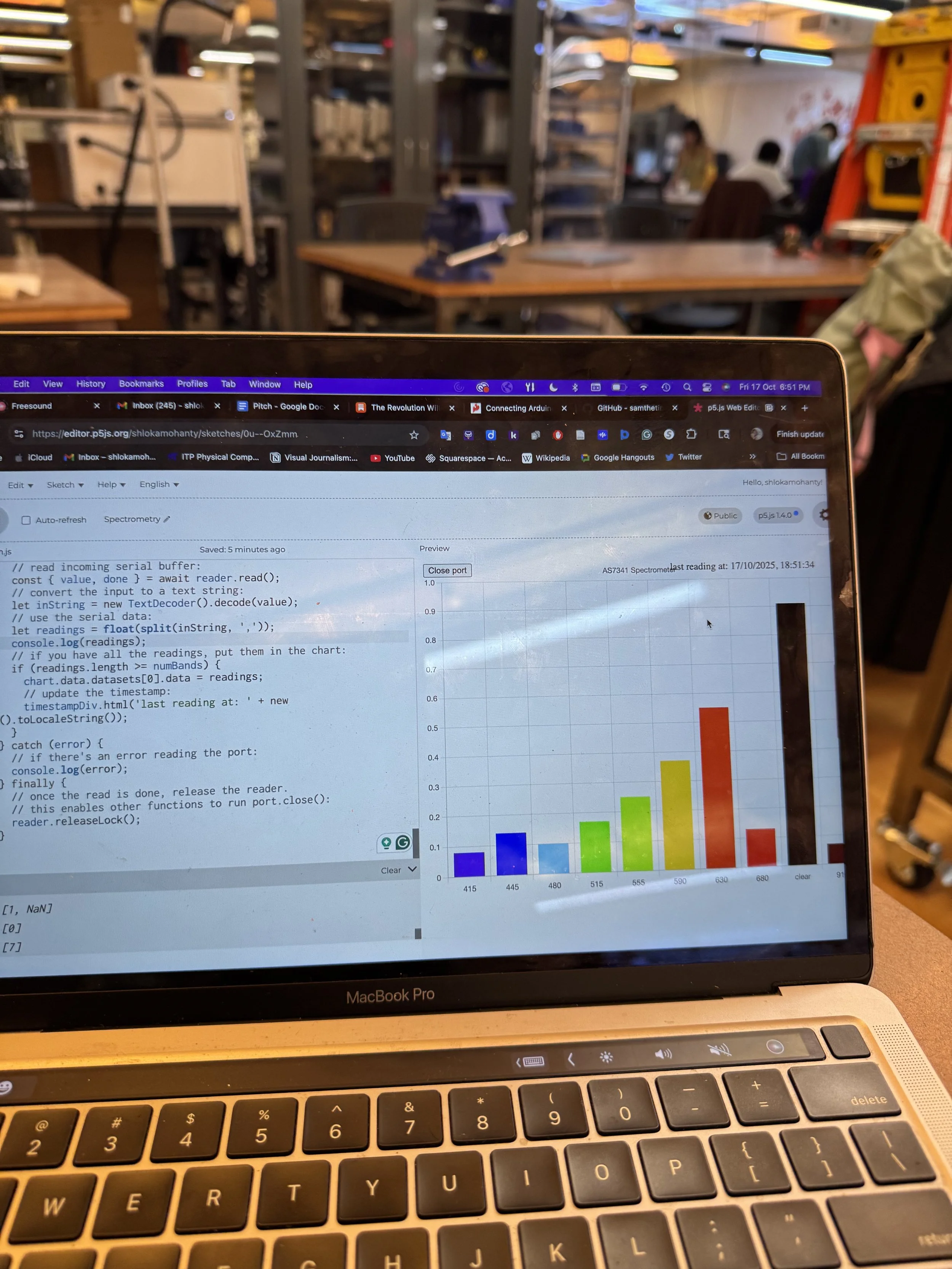
So the next day, I revamped my code after referring to Tom's notes, and I was able to establish serial communication using Arduino and the p5.webserial, and I used the Spectrograph code, which was written for serial input from AS7341.
/*
  AS7341 sensor readings.  Reads and prints the results
  as a CSV string. This version uses a non-blocking
  approach, using the startReading() and checkReadingProgress()
  functions. It's about 2 seconds between readings.
  Details for this sensor can be found on the AMS product page here:
  https://ams-osram.com/products/sensor-solutions/ambient-light-color-spectral-proximity-sensors/ams-as7341-11-channel-spectral-color-sensor
  In particular, the product data sheet, user guide, and
  Application Note AS7341 AN000633, "Spectral Sensor Calibration Methods"
  are of most use.

  Library:
  http://librarymanager/All#Adafruit_AS7341

  created 18 Jun 2021
  modified 16 Feb 2025
  by Tom Igoe
*/

#include <Adafruit_AS7341.h>
// instance of the sensor library:

Adafruit_AS7341 as7341;
// array to hold the raw readings:
uint16_t readings[12];
float channels[12];
// header string for CSV:
String headers = "415nm,445nm,480nm,515nm,555nm,590nm,630nm,680nm,Clear,NIR";
// correction factors:  these corrections are from Application Note AS7341 AN000633, "Spectral Sensor Calibration Methods"
// fig. 10. These are for channels F1 through F8.
// TODO: This math needs to be corrected.
// values 4 and 5 are 0 because they are not used (see datasheet)
float corrections[] = { 3.20, 3.00, 2.07, 1.30, 0.0, 0.0, 1.07, 0.93, 0.78, 0.71 };

void setup() {
  // init serial, wait 3 secs for serial monitor to open:
  Serial.begin(9600);
  // if the serial port's not open, wait 3 seconds:
  if (!Serial) delay(50);

  if (!as7341.begin()) {
    Serial.println("Sensor not found, check wiring");
    while (true)
      ;
  }

  // set integration time:
  as7341.setATIME(100);
  as7341.setASTEP(999);
  as7341.setGain(AS7341_GAIN_256X);
  // print column headers:
  Serial.println("setup");
  Serial.println(headers);
  // start a new reading cycle:
  as7341.startReading();
}

void loop() {
  if (!as7341.checkReadingProgress()) return;

  // if the current reading is complete:
    if(readSensor()) {
    // print the results:
    for (int r = 0; r < 12; r++) {
      // skip readings 4 and 5 as they are repeats:
      if (r == 4 || r == 5) continue;
      Serial.print(channels[r]);
      if (r < 11) Serial.print(",");
    }
    Serial.println();
    // start a new reading cycle:
    as7341.startReading();
  }
}

bool readSensor() {
  // take the current reading, do corrections,
  // and put the result into readingString:
  // get the readings:
  if (!as7341.readAllChannels(readings)) return false;
  // there are 12 elements in the readAllChannels array,
  // but elements 4 and 5 are not used. So channel number is different
  // than array index:
  int channelNum = 0;
  // loop over the readings and put them in the channels array:
  for (int r = 0; r < 12; r++) {
    // skip readings 4 and 5 as they are repeats:
    if (r == 4 || r == 5) continue;
    channels[r] = as7341.toBasicCounts(readings[r]);
    if (r < 10) {
      channels[r] = channels[r] * corrections[r];
    }
  }
  return true;
}
After that, I was getting values from the spectrograph, but I couldn't tell how far it was detecting.


So, I went to the shop and talked to Nikolai and Nasif to understand exactly what a diffuser is and whether I should purchase one based on the documentation I saw for the diffuser: https://look.ams-osram.com/m/436a32f63ba06bad/original/AS7341-Details-for-Optomechanical-Design.pdf.
But they showed me how to make a diffuser using acetate paper. I used P3000 and P2500 sandpaper and sanded the acetate paper. After it got a frosted texture, I placed it over the sensor and continued detecting, but the results remained confusing to me. But at this point, I was still trying to detect from really far.
Then Prisha comes over and tells me that I need to put the object really close to the sensor. She put her green scarf right over the sensor, and that's when I realised how close you have to be to the sensor to detect the colors. For some reason, the sensor also detected better without the diffuser than with it, so I decided to let go of the diffuser.

In the meantime, as a backup, I listened to Prisha's advice and decided to try out the hall-effect sensors, which could be connected to the breadboard like potentiometers. This is what I had coded for it. I decided that I’d give myself until next Wednesday to configure the sensor, or else switch to a different one.
void setup() {
  // put your setup code here, to run once:
  Serial.begin(9600);
}

void loop() {
  // put your main code here, to run repeatedly:
  Serial.println(analogRead(A6));
}
Prisha gives me the idea of printing and cutting colored circles, putting them right over the sensor, and mapping the values.
I was then confused about which colors to map to the sensor or even how to start mapping values, so I talked to Arjun, and he told me to try mapping the values to the red, blue, and green ranges since that would be easier.

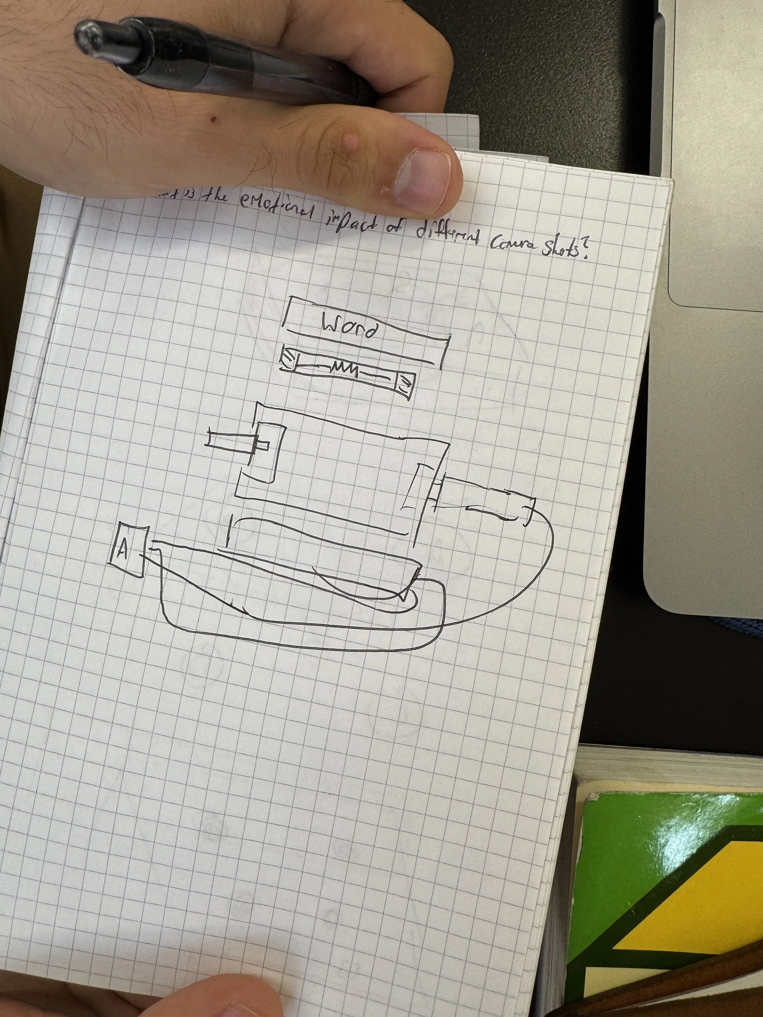
After talking to Arjun, I planned my project again using just one sensor. Furthermore, in class, after talking to Tom about my project, I also wrote down all the possible questions I had while making a diagram of what the project might look like and roughly planning a schedule, which I didn't end up sticking to.
So the next week, I started mapping values. I began mapping values and creating general functions in p5. I ended up hard-coding the range. Based on the ranges I got.


But the manner in which I mapped it, and when I used that to detect the values. The readings spanned a range such that green and blue were within red's range.

I showed my numbers to Prisha too. She was concerned about the delay in serial communication between Arduino and p5. She suggested I remove delay() and use millis(), and explained how millis() works.
Then I spoke with Guy, who is good with mathematics, but he wasn't able to quite understand the readings. Then I spoke more with William. I showed him my numbers and code, and he was baffled. Then I asked James for help, but he was also really confused about the numbers. But James told me to use LEDs to map the values. Then I was talking to Arjun, and I said to him that I spent the whole day mapping on paper, and he told me that next time I should run my experiments with people before I actually start doing them, so I spend less time. I realised I had spent the whole weekend working with this, and that is quite a long time trying to do it myself. Until the very end, I realised it wasn't working, but that's alright. I learnt to manage my time better and a bit more about the project process.
The next day, I had office hours with Christina Tang. She told me I don't need to use LEDs because the spectrometer is reading the wavelengths fine. I showed her the code, since I had doubts about values 4 and 5, which aren't used. Christina said that the corrections Tom is making may be based on his own spectrometer readings. She told me to use the weighted values of each RGB reading and then try to identify the values.
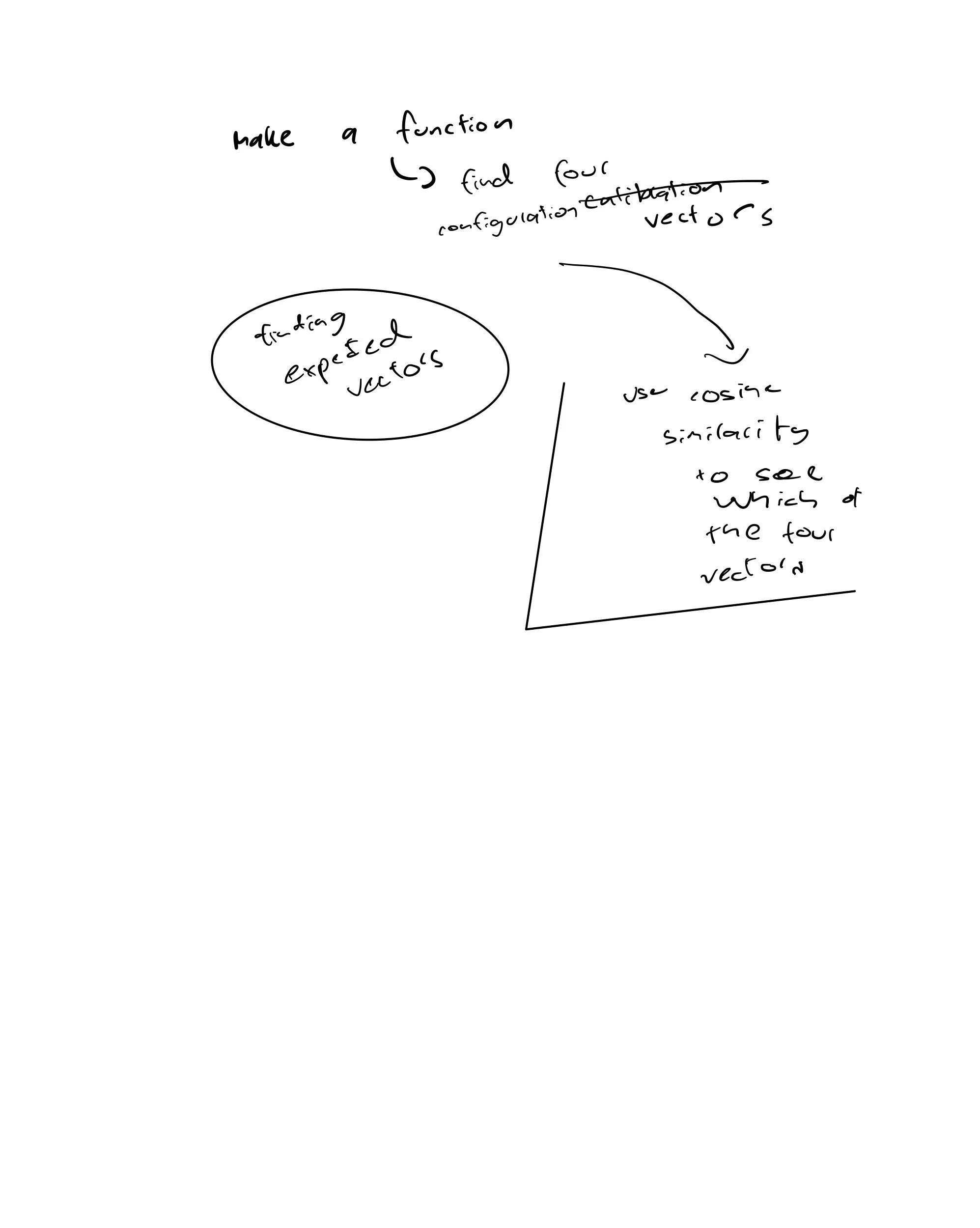
Then I needed more help with the code's process, so I went up to James, and he explained that I should use cosine similarity to identify the colors. He explained that I should create calibration/configuration vectors, but I didn't know what that meant.
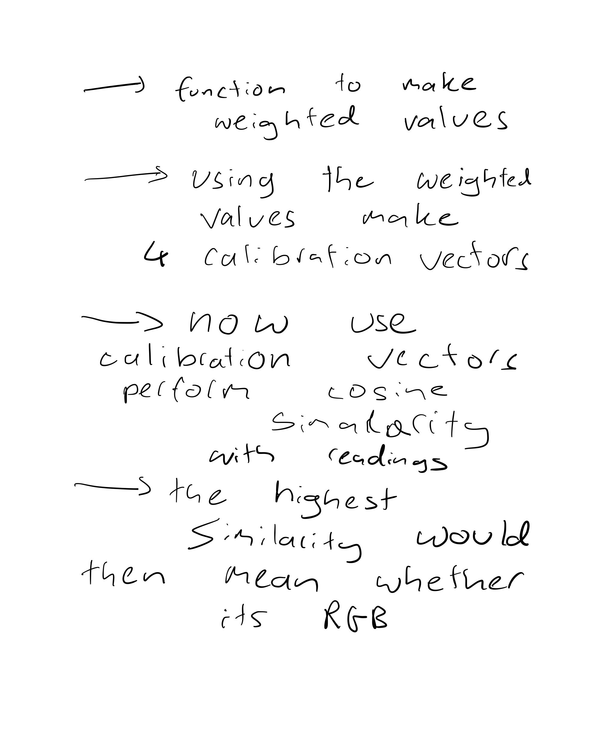
So later, I asked him again, and he explained precisely what it meant. Then I came up with a plan on how to form the code.
I asked Tom about the 4 and 5 readings in the next class, and he mentioned that the corrections are from the datasheet, not from his own spectrometer.
So the next few days went into debugging the code, I let go of the Wednesday deadline since each time I debugged the code, I felt like I was really close to the solution. I also accepted by then that I wanted to challenge myself and work with this sensor, even though my project might end up failing.
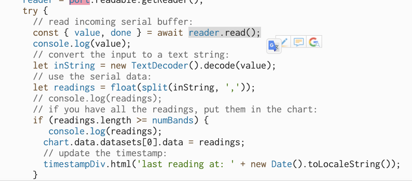
One of the biggest issues that I ran into with my code was the delay. Serial communication between the Arduino and p5.js was taking a while. So I talked to Nikolai and James. They told me that the Arduino is reading 10 values, but then, because of how the serial communication is set up, the values are sent in ASCII. This part of the code was confusing, as it caused some of the signals not to be in 10s. Nikolai also gave me TCS3200, which is another color sensor to work with as it reads RGB values.
So I emailed Tom to ask why, and he said the delay isn't because the code was sent in ASCII. That's happening in about 0.004 seconds. It's because the sensor needs time to take its readings —typically a couple of seconds. Any other delays in your code or the transmission will be irrelevant relative to the sensor integration time (aka the time it needs to read).
// adapted from https://stackoverflow.com/questions/31174001/javascript-multiple-arrays-in-object
/*
  Spectrograph
  Written for serial input from AS7341, but could be adapted
  for other spectrometers, and for other transport mechanisms.

  Assumes a set of comma-separated values.

  uses p5.js and webSerial.
*/
// Serial port elements:
let port;               // the serial port
let reader;             // port reader object
let writer;             // port writer object
let keepReading = true; // keeps the listenForSerial loop going
let serialReadPromise;  // Promise for the listenForSerial function

let recycling;
let compost;
let general_trash;
let correct;
let wrong;


let trash_setting;  // setting for trash bin
// the DOM elements that might be changed by various functions:
let portButton;   // the open/close port button

let timestampDiv;
// fill in wavelengths of your spectrometer here:
let wavelengths = [415, 445, 480, 515, 555, 590, 630, 680, 'clear', 910];
let numBands = 10;

// array to put the readings from the sensors into:
let readings = new Array();
// instance of the token:
let token;

var wavelength_415;
var wavelength_445;
var wavelength_480;
var wavelength_515;
var wavelength_555;
var wavelength_590;
var wavelength_630;
var wavelength_680;
var wavelength_clear;
var wavelength_910;

var green_token_vals = {
  token: [
    [0, 0.01, 0.01, 0.02, 0.01, 0.01, 0.01, 0, 0.03, 0],
    [0, 0.01, 0.01, 0.02, 0.01, 0.01, 0.01, 0, 0.03, 0],
    [0, 0.01, 0.01, 0.02, 0.01, 0.01, 0.01, 0, 0.03, 0],
    [0, 0.01, 0.01, 0.02, 0.01, 0.01, 0.01, 0, 0.03, 0],
    [0, 0, 0, 0.01, 0.01, 0, 0.01, 0, 0.02, 0],
    [0, 0, 0, 0.01, 0.01, 0, 0.01, 0, 0.02, 0],
    [0.01, 0.01, 0.02, 0.02, 0.02, 0.01, 0.02, 0.01, 0.02, 0],
    [0, 0, 0.01, 0.01, 0.01, 0.01, 0.01, 0, 0.02, 0],
    [0, 0, 0.01, 0.01, 0.01, 0.01, 0.01, 0, 0.02, 0],
    [0, 0, 0.01, 0.01, 0.01, 0.01, 0.01, 0, 0.02, 0]
  ]
};

var red_token_vals = {
  token: [[0.01, 0.01, 0.01, 0.01, 0.01, 0.01, 0.06, 0.03, 0.07, 0.01],
  [0.01, 0.01, 0, 0, 0, 0.01, 0.04, 0.02, 0.05, 0],
  [0.01, 0.01, 0.01, 0, 0, 0.01, 0.05, 0.02, 0.06, 0.01],
  [0.01, 0.01, 0.01, 0, 0, 0.01, 0.05, 0.02, 0.06, 0.01],
  [0.01, 0.01, 0.01, 0, 0, 0.01, 0.05, 0.02, 0.06, 0.01],
  [0.01, 0.01, 0.01, 0, 0, 0.01, 0.05, 0.02, 0.06, 0.01],
  [0.01, 0.01, 0.01, 0, 0, 0.01, 0.05, 0.02, 0.06, 0.01],
  [0.01, 0.01, 0.01, 0, 0, 0.01, 0.05, 0.02, 0.06, 0.01],
  [0.02, 0.02, 0.01, 0.01, 0.01, 0.02, 0.1, 0.09, 0.15, 0.02],
  [0.01, 0.01, 0, 0, 0, 0.01, 0.05, 0.02, 0.06, 0.01],
  [0.01, 0.01, 0, 0, 0, 0.01, 0.05, 0.02, 0.06, 0.01]
  ]
};

var blue_token_vals = {
  token: [[0.07, 0.17, 0.24, 0.12, 0.11, 0.08, 0.11, 0.04, 0.28, 0.03],
  [0.01, 0.13, 0.18, 0.03, 0.01, 0, 0, 0, 0.09, 0],
  [0, 0.03, 0.04, 0.01, 0, 0, 0, 0, 0.02, 0],
  [0, 0.03, 0.04, 0.01, 0, 0, 0, 0, 0.03, 0],
  [0, 0.03, 0.04, 0.01, 0, 0, 0, 0, 0.03, 0],
  [0, 0.03, 0.04, 0.01, 0, 0, 0, 0, 0.03, 0],
  [0, 0.03, 0.04, 0.01, 0, 0, 0, 0, 0.02, 0],
  [0, 0.03, 0.04, 0.01, 0, 0, 0, 0, 0.02, 0],
  [0, 0.03, 0.03, 0.01, 0, 0, 0, 0, 0.02, 0],
  [0, 0.03, 0.03, 0.01, 0, 0, 0, 0, 0.02, 0],
  [0, 0.03, 0.04, 0.01, 0, 0, 0, 0, 0.02, 0],
  [0, 0.03, 0.04, 0.01, 0, 0, 0, 0, 0.02, 0],
  [0, 0.03, 0.04, 0.01, 0, 0, 0, 0, 0.02, 0]
  ]
};

// data object for the token:
const data = {
  labels: wavelengths,
  datasets: [{
    label: 'AS7341 Spectrometer',
    data: new Array(),
    backgroundColor: new Array()
  }]
};

function sum(arr) {
  return arr.reduce(function (a, b) {
    return a + b;
  }, 0);
}

function average(arr) {
  if (arr.length === 0) {
    return 0;
  }
  let sum = 0;
  for (let i = 0; i < arr.length; i++) {
    sum += arr[i];
  }
  return sum / arr.length;
}

function cosine_similarity(vector1, vector2) {
  console.log('vector1: ', vector1);
  console.log('vector2: ', vector2);
  let result = 0;
  for (let i = 0; i < vector1.length; i++) {
    result += vector1[i] * vector2[i];
  }
  cosine = result / float((sum(vector1) * sum(vector2)) ** 0.5)
  console.log('cosine: ', cosine);
  return cosine;
}

function get_largest(a, b, c, d) {
  return Math.max.apply(null, arguments)
}


function preload() {
  general_trash_img = loadImage('Screenshot 2025-10-25 at 7.22.29 PM.png');
  recycling_img = loadImage('Screenshot 2025-10-25 at 7.22.17 PM.png');
  compost_img = loadImage('Screenshot 2025-10-25 at 7.22.24 PM.png');
  soundFormats('mp3');
  song1 = loadSound('incorrect-293358.mp3');
  song2 = loadSound('sonido-correcto-331225.mp3');
}

let wavelengths_415 = [];
let wavelengths_445 = [];
let wavelengths_480 = [];
let wavelengths_515 = [];
let wavelengths_555 = [];
let wavelengths_590 = [];
let wavelengths_630 = [];
let wavelengths_680 = [];
let wavelengths_clear = [];
let wavelengths_910 = [];

function token_val_array(token_vals) {
  for (var key in token_vals) {
    token_vals[key].forEach(
      function (elem) {
        var wavelength_415 = elem[0];
        var wavelength_445 = elem[1];
        var wavelength_480 = elem[2];
        var wavelength_515 = elem[3];
        var wavelength_555 = elem[4];
        var wavelength_590 = elem[5];
        var wavelength_630 = elem[6];
        var wavelength_680 = elem[7];
        var wavelength_clear = elem[8];
        var wavelength_910 = elem[9];

        wavelengths_415.push((elem[0]));
        wavelengths_445.push((elem[1]));
        wavelengths_480.push((elem[2]));
        wavelengths_515.push((elem[3]));
        wavelengths_555.push((elem[4]));
        wavelengths_590.push((elem[5]));
        wavelengths_630.push((elem[6]));
        wavelengths_680.push((elem[7]));
        wavelengths_clear.push((elem[8]));
        wavelengths_910.push((elem[9]));
      })
  }
}

token_val_array(green_token_vals);

green_token_character_vector = [average(wavelengths_415), average(wavelengths_445), average(wavelengths_480), average(wavelengths_515), average(wavelengths_555), average(wavelengths_590), average(wavelengths_630), average(wavelengths_680), average(wavelengths_clear), average(wavelengths_910)];

token_val_array(red_token_vals);

red_token_character_vector = [average(wavelengths_415), average(wavelengths_445), average(wavelengths_480), average(wavelengths_515), average(wavelengths_555), average(wavelengths_590), average(wavelengths_630), average(wavelengths_680), average(wavelengths_clear), average(wavelengths_910)];

token_val_array(blue_token_vals);

blue_token_character_vector = [average(wavelengths_415), average(wavelengths_445), average(wavelengths_480), average(wavelengths_515), average(wavelengths_555), average(wavelengths_590), average(wavelengths_630), average(wavelengths_680), average(wavelengths_clear), average(wavelengths_910)];

// token_val_array(no_token_vals);

// no_token_character_vector = [average(wavelengths_415), average(wavelengths_445), average(wavelengths_480), average(wavelengths_515), average(wavelengths_555), average(wavelengths_590), average(wavelengths_630), average(wavelengths_680), average(wavelengths_clear), average(wavelengths_910)];

function type_correct(flowerX, flowerY, petalSize) {
  // console.log("correct!");
  let petalDistance = petalSize / 2;
  fill(116, 195, 99, alpha);
  textSize(petalSize);
  text('correct', flowerX - petalDistance, flowerY - petalDistance);
  alpha = alpha - fadeAmount;
  if (alpha < 0) {
    alpha = 0;
    // noLoop();
  }
}

function type_wrong(flowerX, flowerY, petalSize) {
  let petalDistance = petalSize / 2;
  fill(211, 26, 56, alpha);
  textSize(petalSize);
  text('wrong', flowerX - petalDistance, flowerY - petalDistance);
  alpha = alpha - fadeAmount;
  if (alpha < 0) {
    alpha = 0;
    // noLoop();
  }
}

function setup() {
  createCanvas(900, 600);
  portButton = createButton("Open port");
  portButton.position(10, 10);
  portButton.mousePressed(openClosePort);
  trash_setting = int(random(0, 2));
  alpha = 255;
  fadeAmount = 255 / 10;
  frameRate(2)
}

function draw() {
  background(220);
  background(255, 255, 255);
  noStroke()
  fill(204, 189, 189);
  beginShape();
  vertex(width / 2 + 100, height / 2 - 100);
  vertex(width / 2 - 100, height / 2 - 100);
  vertex(width / 2 - 50, height);
  vertex(width / 2 + 50, height);
  endShape(CLOSE);
  if (trash_setting == 0) {
    image(general_trash_img, 408, 350, 90, 85);
  } else if (trash_setting == 1) {
    image(recycling_img, 408, 350, 90, 85);
  }
  if (correct == true) {
    type_correct(random(width), random(height), random(10, 100));
  }
  if (wrong == true) {
    type_wrong(random(width), random(height), random(10, 100));
  }
}

////////////////////

async function openClosePort() {
  console.log("port opened");
  // if the browser supports serial:
  if ("serial" in navigator) {
    // if the port exists, it's likely open. Close it:
    if (port) {
      // set keepReading false to stop the listenForSerial loop:
      keepReading = false;
      // stop the reader, so you can close the port:
      reader.cancel();
      // wait for the listenForSerial function to stop:
      await serialReadPromise;
      // close the serial port itself:
      await port.close();
      // change the button label:
      portButton.html("open port");
      // clear the port variable:
      port = null;
    } else {
      // if the port is null, try to open it:
      try {
        // pop up window to select port:
        port = await navigator.serial.requestPort();
        // set port settings and open it:
        await port.open({ baudRate: 9600 });
        // enable the listenForSerial loop:
        keepReading = true;
        // start the listenForSerial function:
        serialReadPromise = listenForSerial();
        // change the button label:
        portButton.html("Close port");
      } catch (err) {
        // if there's an error opening the port:
        console.error("There was an error opening the serial port:", err);
      }
    }
  }
}

async function sendData(data) {
  // if the port's open and readable:
  if (port) {
    if (port.readable) {
      // initialize the writer:
      writer = port.writable.getWriter();
      // convert the data to be sent to an array:
      var output = new TextEncoder().encode(data);
      // send it, then release the writer:
      writer.write(output).then(writer.releaseLock());
    }
  }
}

async function listenForSerial() {
  // console.log("listening for serial data");
  // while the port is open and keepReading is true:
  while (port.readable && keepReading) {
    // console.log('inside listenForSerial loop');
    // initialize the reader:
    reader = port.readable.getReader();
    try {
      // read incoming serial buffer:
      const { value, done } = await reader.read();
      // console.log('got reading');
      // convert the input to a text string:
      let inString = new TextDecoder().decode(value);
      // console.log('inString: ', inString);
      // console.log('inString: ', inString);
      // use the serial data:
      readings = float(split(inString, ','));
      // if you have all the readings, put them in the token:
      if (readings.length >= numBands) {
        readings = readings.map(item => (isNaN(item) ? 0 : item));
        console.log('readings: ', readings);
        green_cosine = cosine_similarity(green_token_character_vector, readings);
        blue_cosine = cosine_similarity(blue_token_character_vector, readings);
        red_cosine = cosine_similarity(red_token_character_vector, readings);
        // no_token_cosine = cosine_similarity(no_token_character_vector, readings);
        let largest = get_largest(green_cosine, blue_cosine, red_cosine);
        console.log('largest: ', largest);
        if (trash_setting == 0) {
          if (largest == red_cosine) {
            correct = true;
            song2.play();
          } else {
            wrong = true;
            song1.play();
          }
        } else if (trash_setting == 1) {
          if (largest == blue_cosine) {
            correct = true;
            song2.play();
          } else {
            wrong = true;
            song1.play();
          }
        }
      }
      else {
        console.log('not enough bands: ' + readings.length);
      }
    } catch (error) {
      // token.data.datasets[0].data = readings;
      // update the timestamp:
      // timestampDiv.html('last reading at: ' + new Date().toLocaleString());
      // if there's an error reading the port:
      console.log('error: ', error.toString());
    } finally {
      // once the read is done, release the reader.
      // this enables other functions to run port.close():
      reader.releaseLock();
    }
  }
}
So after my new plan for designing the trash can, I talked to Ian from the shop, and he told me to use acrylic to fabricate, since I need a material through which the LED light can shine. He helped me look through the junk shelf and found a huge piece of acrylic.
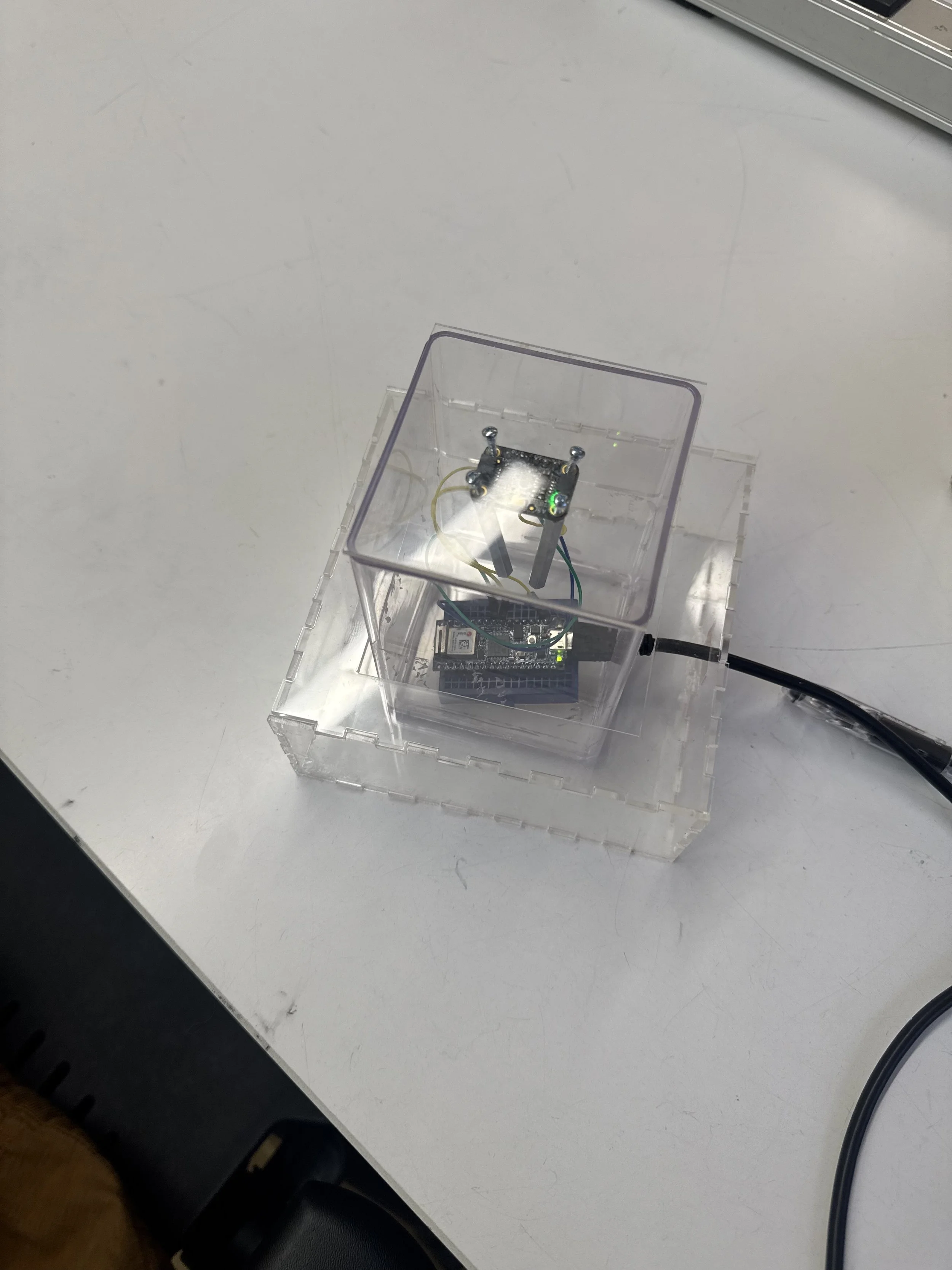
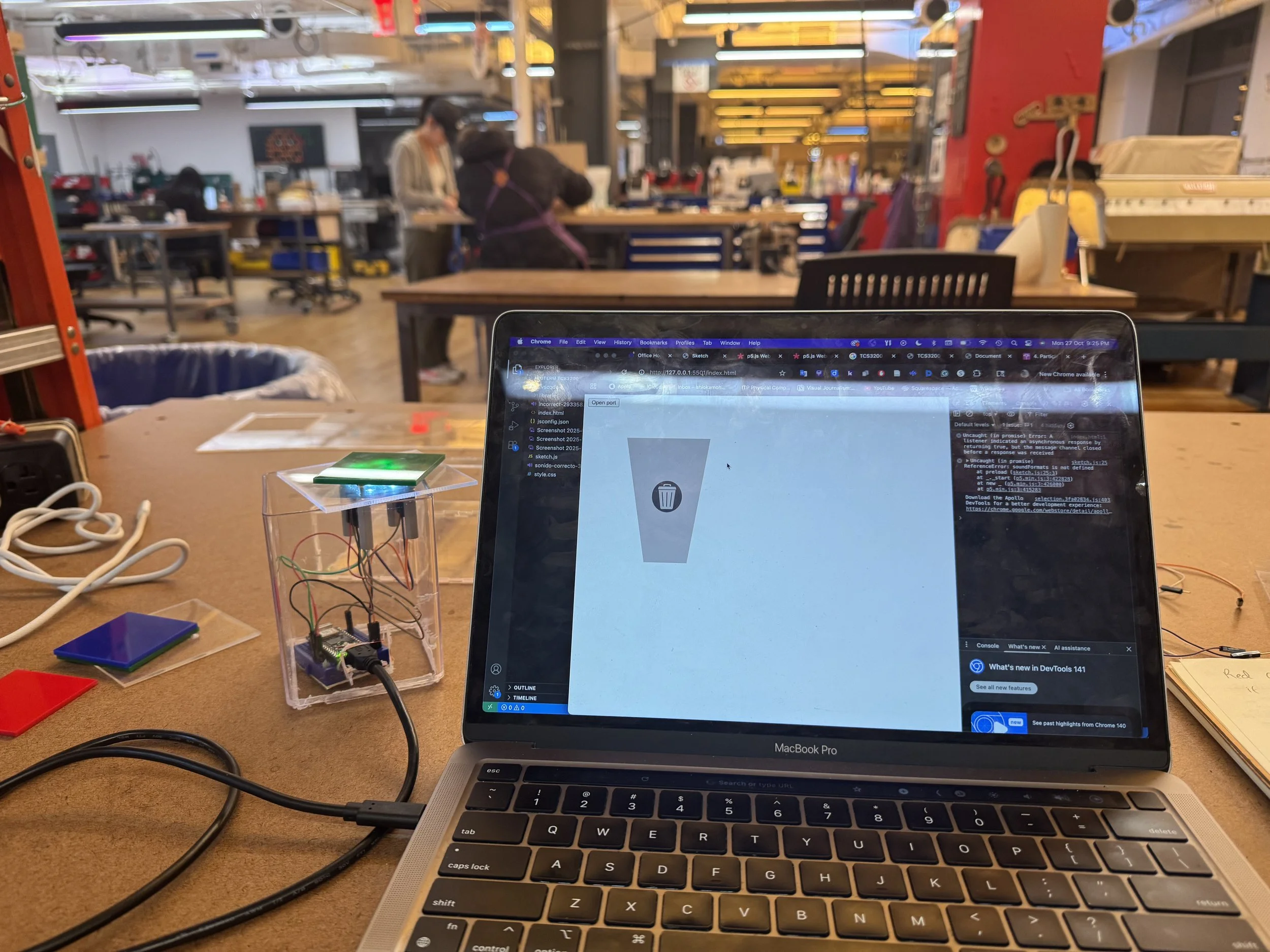
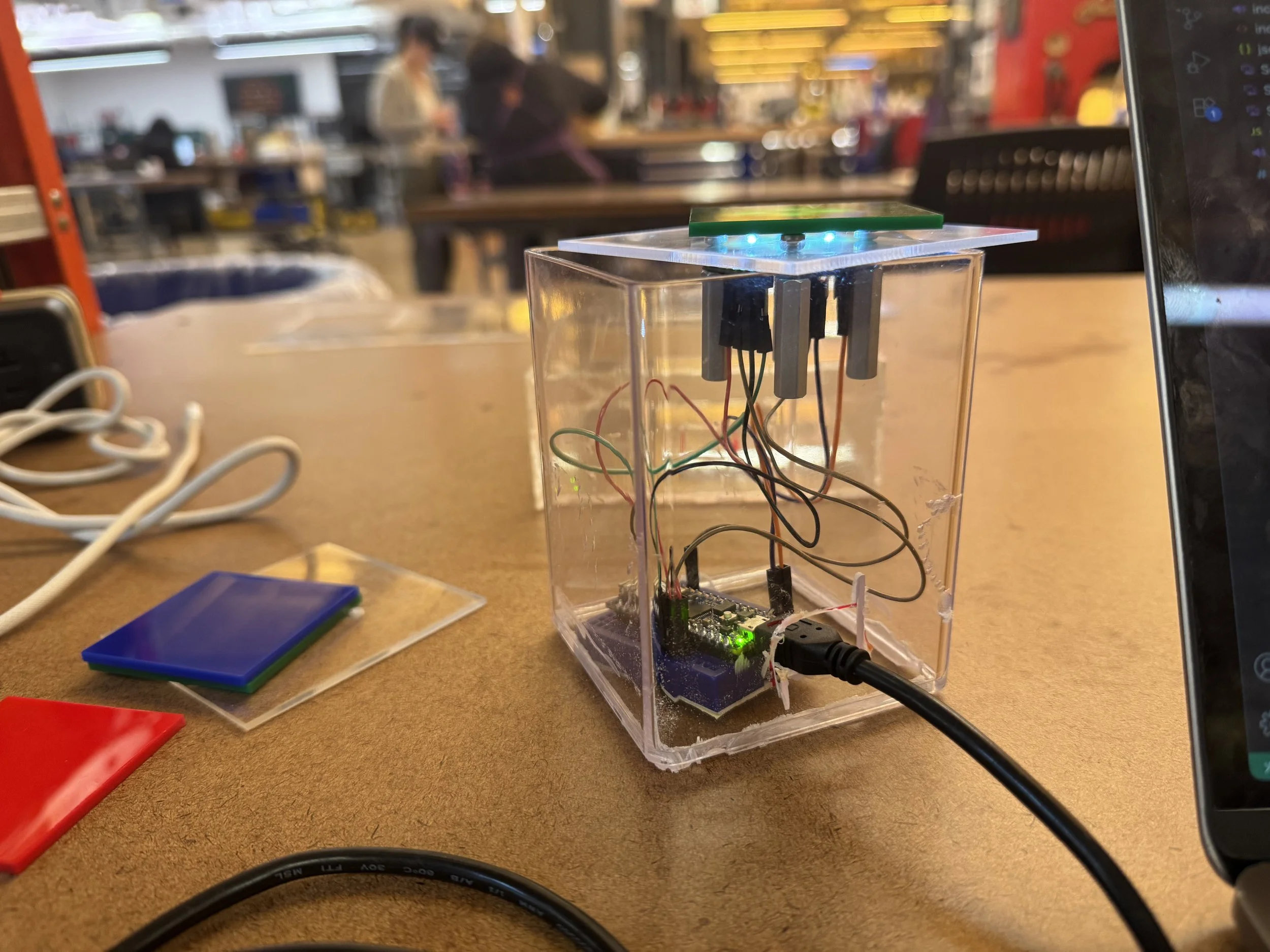
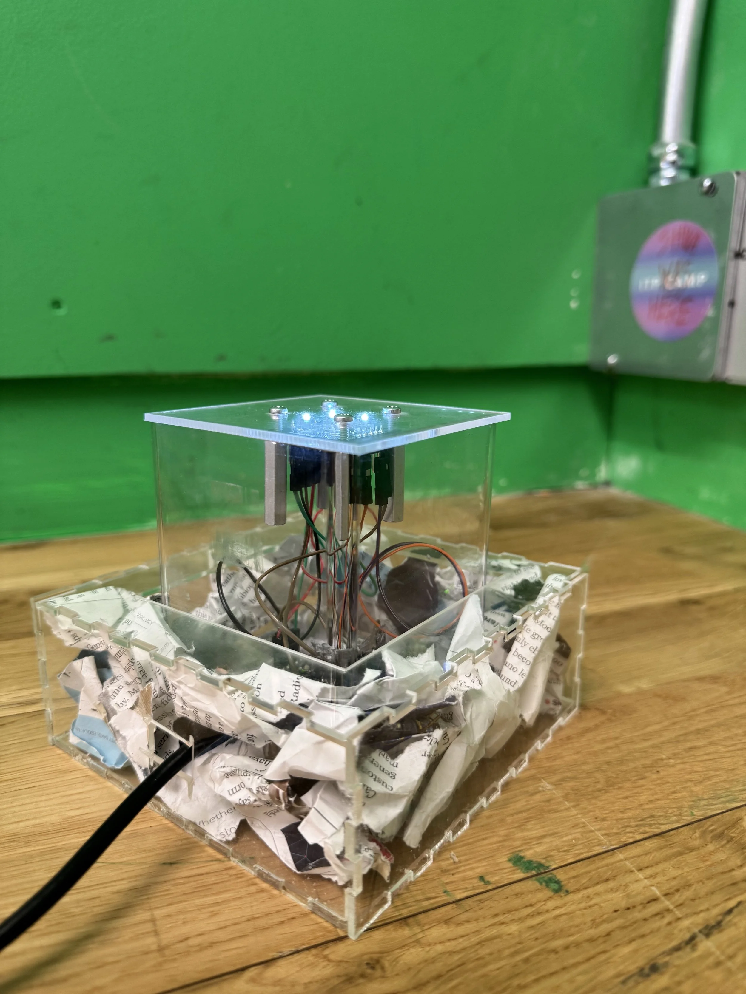
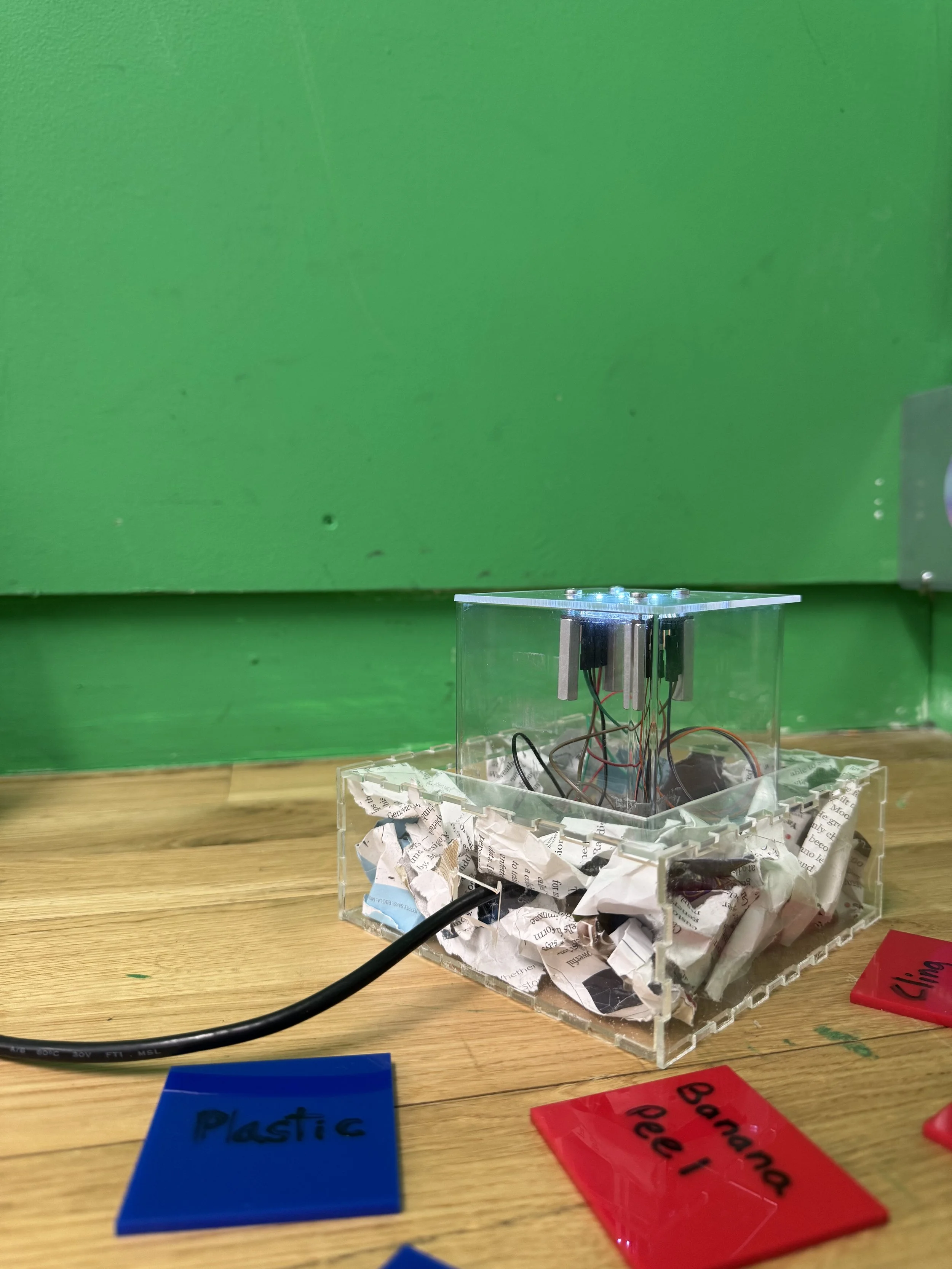
On Saturday, I took a break from debugging the code and decided to start fabricating. I was talking to people in the Shop, and initially, my plan was to 3D print a trash chute. Instead, they suggested I buy a pencil holder or a mini trash chute from somewhere nearby. Then I bought a clear pencil holder from Target. I drilled small holes along the edges of the pencil holder, then used the Dremel to drill a hole through it. To make the box, I used Makercase to design it, then laser-cut it from acrylic. Ian had given me standoffs and screws that would work with the sensor. So I used a digital caliper and measured the holes on the sensor to make holes on the acrylic lid. Then I assembled everything and continued debugging the code. Aram showed me how to connect the Arduino to the busless breadboard.
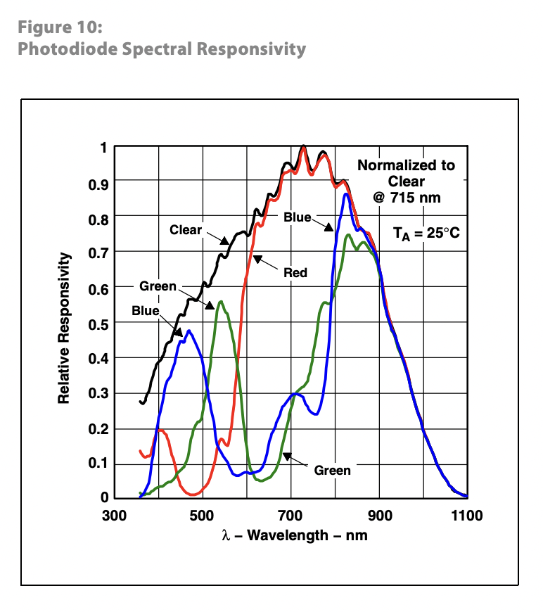
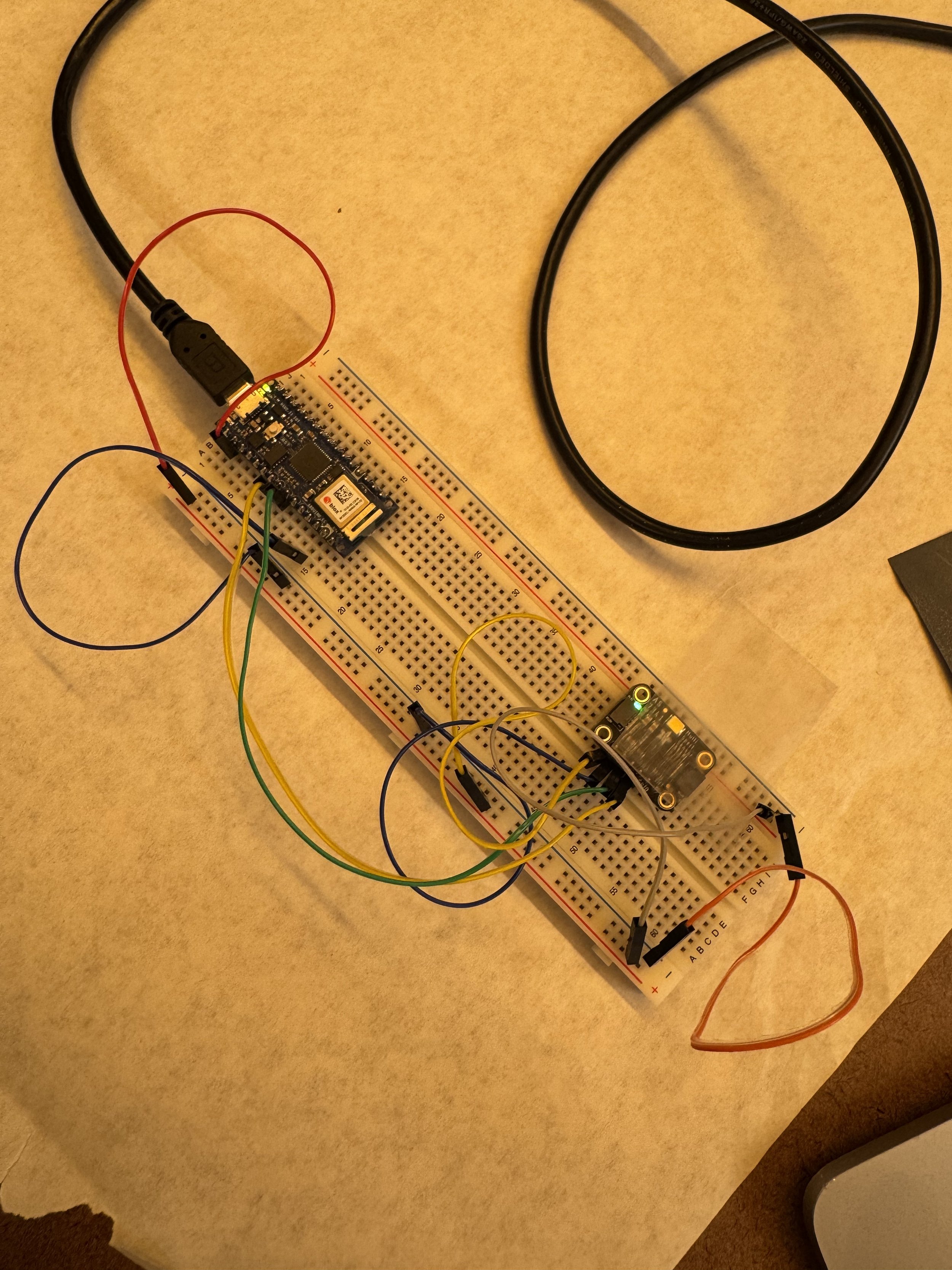
Then on Sunday, by the time I was done. The code couldn't thoroughly read green, and there was a significant delay. Nikolai gave me his TCS3200 sensor to work with for the midterm, since it is easier to code with. I playtested the game with William, and he told me I should switch to the other sensor. I started coding with the other sensor, and then talked to Tom on Monday. He showed me this diagram, which is when I understood why green is difficult to read.
TCS3200 before fabricating.
On Monday, I spent the day fabricating for TCS3200. Alanna showed me how to connect the TCS3200 sensor to an Arduino on a busless breadboard. I also got standoffs from the Shop. Unfortunately, since the standoffs were metal, S1 started going to ground. Cody helped me debug this. Then I worked on the code until 5 am. I kept running into an error: the sensor readings were too fast, so I had to figure out a condition that wouldn't change the token condition every time there was a new reading, and only react when a token has been moved.
// Serial port elements:
let port;               // the serial port
let reader;             // port reader object
let writer;             // port writer object
let keepReading = true; // keeps the listenForSerial loop going
let serialReadPromise;  // Promise for the listenForSerial function
const chunkedReadings = [];
const chunkSize = 3;

// the DOM elements that might be changed by various functions:
let portButton;   // the open/close port button

let timestampDiv;
let numBands = 3;
let trash_setting;
let correct;
let wrong;
// array to put the readings from the sensors into:
let readings = new Array();
let readings_list = new Array();

function preload() {
  general_trash_img = loadImage('Screenshot 2025-10-25 at 7.22.29 PM.png');
  recycling_img = loadImage('Screenshot 2025-10-25 at 7.22.17 PM.png');
  compost_img = loadImage('Screenshot 2025-10-25 at 7.22.24 PM.png');
  chocolate_wrapper = loadImage("105-1059806_empty-chocolate-wrapper-coloured-drawing-of-an-maltesers.png");
  water_bottle = loadImage("7952188.png");
  soundFormats('mp3');
  song1 = loadSound('incorrect-293358.mp3');
  song2 = loadSound('sonido-correcto-331225.mp3');
}

let red_vals = [];
let green_vals = [];
let blue_vals = [];

// function val_array(vals) {
//   console.log("vals: " + vals);
//   for (var key in vals) {
//   vals[key].forEach(
//     function(elem) {
//     var red_val = elem[0];
//     console.log(red_val);
//     var green_val = elem[1];
//     var blue_val = elem[2];

//     red_vals.push((elem[0]));
//     green_vals.push((elem[1]));
//     blue_vals.push((elem[2]));
//   })
// }
// }


/*
readings = [25,57,49]
key = 25
readings[25]
*/

function get_lowest(a, b, c, d) {
  return Math.min.apply(null, arguments)
}


function sum(arr) {
  return arr.reduce(function (a, b) {
    return a + b;
  }, 0);
}

function average(arr) {
  if (arr.length === 0) {
    return 0;
  }
  let sum = 0;
  for (let i = 0; i < arr.length; i++) {
    sum += arr[i];
  }
  return sum / arr.length;
}

function type_correct(flowerX, flowerY, petalSize) {
  let petalDistance = petalSize / 2;
  fill(116, 195, 99, alpha);
  textSize(petalSize);
  text('correct', flowerX - petalDistance, flowerY - petalDistance);
  alpha = alpha - fadeAmount;
  if (alpha < 0) {
    alpha = 0;
    noLoop();
  }
}

function type_wrong(flowerX, flowerY, petalSize) {
  let petalDistance = petalSize / 2;
  fill(211, 26, 56, alpha);
  textSize(petalSize);
  text('wrong', flowerX - petalDistance, flowerY - petalDistance);
  alpha = alpha - fadeAmount;
  if (alpha < 0) {
    alpha = 0;
    noLoop();
  }
}

function setup() {
  createCanvas(900, 600);
  portButton = createButton("Open port");
  portButton.position(10, 10);
  portButton.mousePressed(openClosePort);
  trash_setting = int(random(0, 2));
  alpha = 255;
  fadeAmount = 255 / 50;
  frameRate(1);
}

function draw() {
  background(220);
  background(255, 255, 255);
  noStroke()
  fill(204, 189, 189);
  beginShape();
  vertex(width / 2 + 100, height / 2 - 100);
  vertex(width / 2 - 100, height / 2 - 100);
  vertex(width / 2 - 50, height);
  vertex(width / 2 + 50, height);
  endShape(CLOSE);
  if (trash_setting == 0) {
    image(general_trash_img, 408, 350, 90, 85);
  } else if (trash_setting == 1) {
    image(recycling_img, 408, 350, 90, 85);
  }
  if (correct == true) {
    type_correct(random(width), random(height), random(10, 100));
    // correct = false;
  } if (wrong == true)  {
    type_wrong(random(width), random(height), random(10, 100));
    // wrong = false;
  }
}

////////////////////

async function openClosePort() {
  // if the browser supports serial:
  if ("serial" in navigator) {
    // if the port exists, it's likely open. Close it:
    if (port) {
      // set keepReading false to stop the listenForSerial loop:
      keepReading = false;
      // stop the reader, so you can close the port:
      reader.cancel();
      // wait for the listenForSerial function to stop:
      await serialReadPromise;
      // close the serial port itself:
      await port.close();
      // change the button label:
      portButton.html("open port");
      // clear the port variable:
      port = null;
    } else {
      // if the port is null, try to open it:
      try {
        // pop up window to select port:
        port = await navigator.serial.requestPort();
        // set port settings and open it:
        await port.open({ baudRate: 9600 });
        // enable the listenForSerial loop:
        keepReading = true;
        // start the listenForSerial function:
        serialReadPromise = listenForSerial();
        // change the button label:
        portButton.html("Close port");
      } catch (err) {
        // if there's an error opening the port:
        console.error("There was an error opening the serial port:", err);
      }
    }
  }
}

async function sendData(data) {
  // if the port's open and readable:
  if (port) {
    if (port.readable) {
      // initialize the writer:
      writer = port.writable.getWriter();
      // convert the data to be sent to an array:
      var output = new TextEncoder().encode(data);
      // send it, then release the writer:
      writer.write(output).then(() => writer.releaseLock());
    }
  }
}


// Persist last_token and token between loop iterations:
let last_token = -1;
let token = 0;

async function listenForSerial() {
  // while the port is open and keepReading is true:
  while (port.readable && keepReading) {
    // initialize the reader:
    reader = port.readable.getReader();
    try {
      // read incoming serial buffer:
      const { value, done } = await reader.read();
    // convert the input to a text string:
    let inString = new TextDecoder().decode(value);
    // use the serial data:
    let readings = split(inString, ',').map(Number);
    if (readings.length >= numBands) {
      let valid = true;
      for (let item of readings) {
        if (isNaN(item) || item === 0) {
          valid = false;
          break;
        } else {
          let red = readings[0];
          let green = readings[1];
          let blue = readings[2];
          console.log('red: ' + red + ' green: ' + green + ' blue: ' + blue);
          let lowest = get_lowest(red, green, blue);
          if (trash_setting == 0) {
            if (red == lowest && red < 30) {
              token = 0;
              if (last_token != token) {
                correct = true;
                wrong = false;
                song2.play();
                last_token = token;
              }
          //  red is not lowest
            } else if (blue == lowest && blue < 40) {
              token = 1;
              if (last_token != token) {
                wrong = true;
                correct = false;
                song1.play();
                last_token = token;
              }
            }
          } else if (trash_setting == 1) {
            if (blue == lowest && blue < 40) {
              token = 0;
              if (last_token != token) {
                correct = true;
                wrong = false;
                song2.play();
                last_token = token;
              }
           } else if (red == lowest && red < 30)  {
            token = 1;
            if (last_token != token) {
              wrong = true;
              correct = false;
              song1.play();
              last_token = token;
        }
          }
        }
        }
      }
    }
    // console.log('readings_list: ' + readings_list);
    // val_array(readings_list);
    // let red_avg = average(red_vals);
    // let green_avg = average(green_vals);
    // let blue_avg = average(blue_vals);
    // console.log('red: ' + red_avg + ' green: ' + green_avg + ' blue: ' + blue_avg
      }
     catch (error) {
      // if there's an error reading the port:
      console.log('error: ', error.toString());
    } finally {
      // once the read is done, release the reader.
      // this enables other functions to run port.close():
      reader.releaseLock();
    }
  }
}
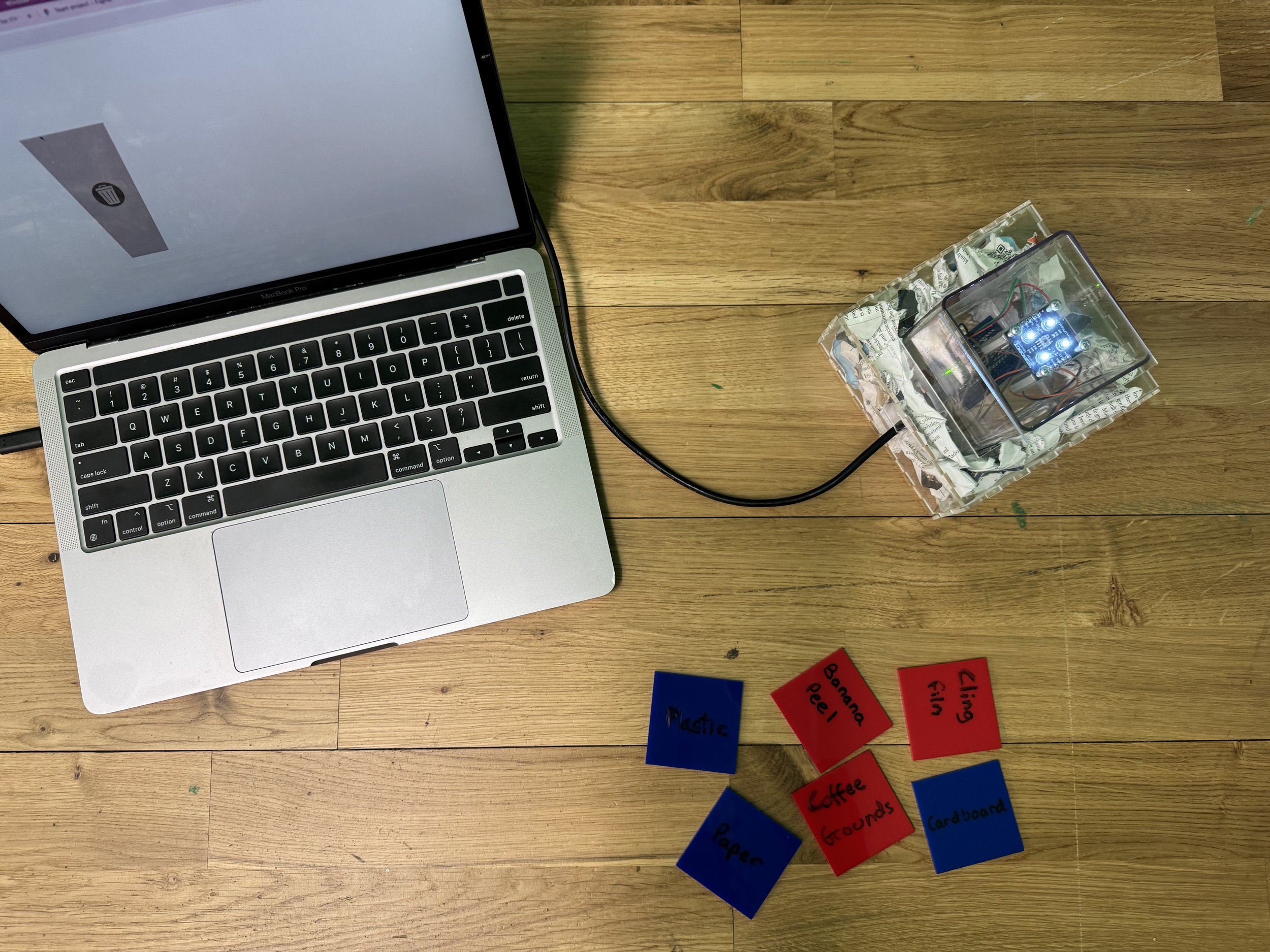
I wasn’t able to figure it out at 5 am and decided that I might present the project as a failure. But then I came back to the school at 9am, and Matt looked at my code and said I just needed to set -1 as my starting condition. It should work, and it did. However, the conditions I set for my game only worked in a specific room, so while presenting in class, the game didn’t work as I intended, but I still learned a lot about sensors.

Midterm Reflection
The midterm taught me a lot about different sensors, which is good, because now, when it comes to planning for the final, I can think more clearly. The midterm also exposed me to many different processes and helped me think about projects more thoroughly. The most important part of the midterm, which I got from the feedback collective, was how to work on the process aspect. Pedro and Alanna told me to work on things in parallel, even if that means experimenting with the sensors. While working on the midterm, I realized I didn't have a proper schedule, but for my final, I will better plan the materials and sensors I might need. The other thing that I learnt from the midterm was how to debug. I ran into issues quite often with my project, and learning to navigate through that by asking people really helped me through my midterm. Another thing I learnt about the midterm is that working alone sometimes means no one holds you accountable, so you have to hold yourself accountable. I gave myself until Wednesday to mess around with the AS7341, but then I got too invested and went down a rabbit hole. Up until 1 day before the midterm, I hadn’t tried a different sensor because I was hell-bent on making this sensor work. So that is something I need to work on when it comes to projects and getting into rabbit holes.