
Week 5
In Class


Assignments
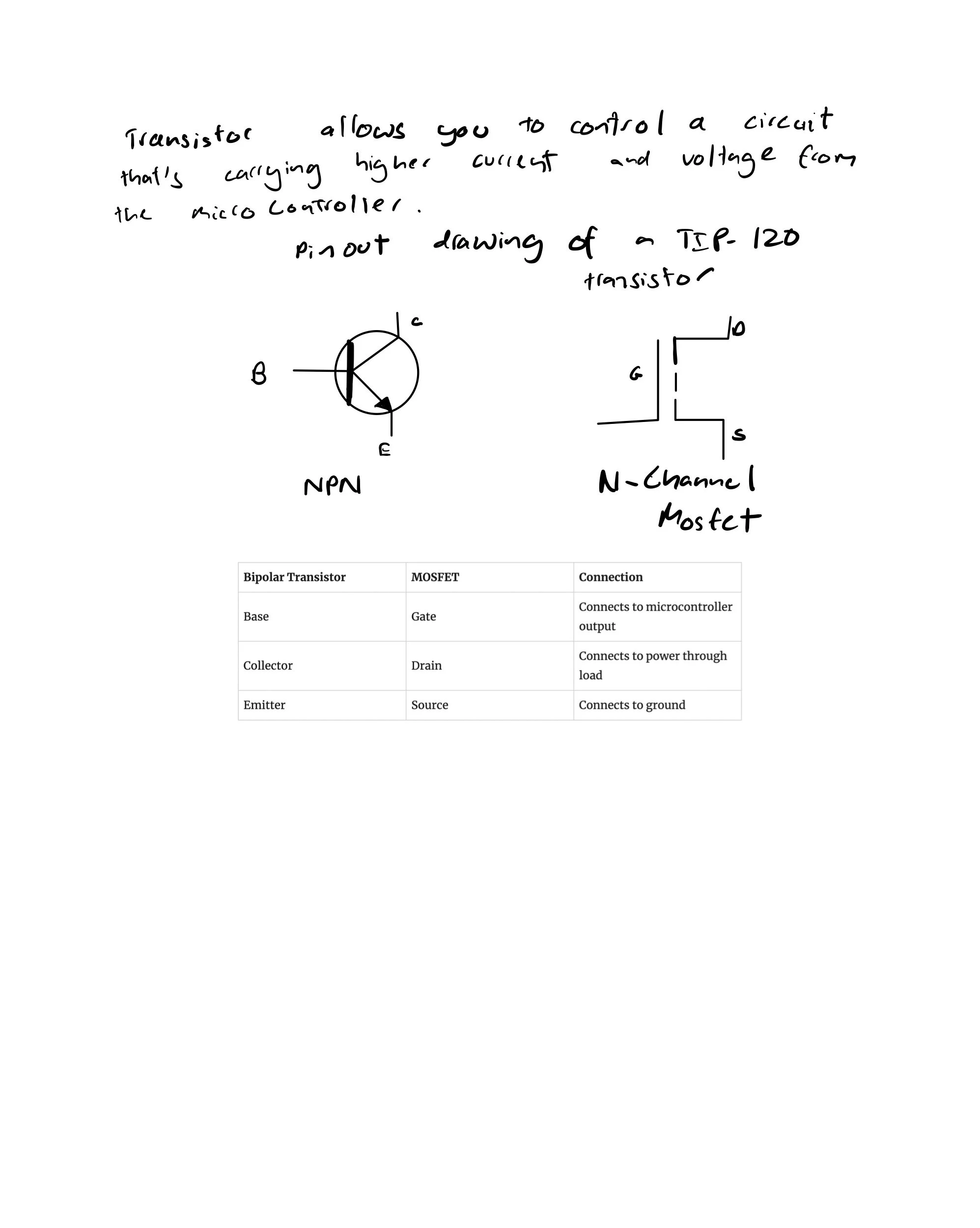
I tried to understand transistors more clearly first before starting the lab.
In the lab, when using a transistor to control high current loads with an Arduino, I initially connected a motor and a power supply, but the motor didn’t work. Then I went over the circuit diagram and realised that my motor was plugged oppositely. The negative side of the motor was connected to the DC power jack, and the positive side of the motor was connected to the transistor. Then, I switched it. It still wasn’t working, then Gabriel helped me realise that I connected the diode to the wrong pin.
const int transistorPin = 9;    // connected to the base of the transistor

 void setup() {
   // set  the transistor pin as output:
   pinMode(transistorPin, OUTPUT);
 }

 void loop() {
   digitalWrite(transistorPin, HIGH);
   delay(1000);
   digitalWrite(transistorPin, LOW);
   delay(1000);
 }
Furthermore, I forgot to upload the code, so nothing was working. Then, after fixing all that, the lab finally ran. But then I realised I wasn’t using a potentiometer.

Then, after that, I tried to light up an LED. Initially, I wasn’t able to figure out which part of the LED was ground and which was power. The multimeter didn’t give any reading. Then, after that, Alanna told me to try powering it directly, and when I did, the LED lit up. I then realised it wasn’t polarized.


Then, when I connected it to the circuit, I tried using a MOSFET to light up the LED, but it didn’t work. Then, Arjun helped me explain the difference between NPN and PNP transistors. When you give voltage to an NPN transistor, the switch closes. However, when you provide voltage to a PNP transistor, the switch opens. In the lab, it states that MOSFETs are more useful for LEDs, but for some reason, the LED only lit up when it was connected to an NPN transistor. Then Arjun helped me realise that the potentiometer isn’t affecting the circuit, and he checked the dataset, explaining that a MOSFET should have worked too. Then I spoke with Alanna, and they told me that because the ground and power weren’t clear in the LED (as in the polarity wasn’t clear), that could affect how the MOSFET transistor works.

Then, in the DC Motor Control Using an H-Bridge Lab, I soldered the motor driver. However, on the right, the lower two pins got connected through the metal alloy, so it took a while to disconnect, and there are some burn marks on it.

Then, in the DC Motor Control Using an H-Bridge Lab, I soldered the motor driver. However, on the right, the lower two pins got connected through the metal alloy, so it took a while to disconnect, and there are some burn marks on them. Then, when I tried connecting the Arduino to my laptop, it didn’t show up. I then connected it to Ryan’s laptop, but it also didn’t show up. Then I realised I had fried my Arduino, possibly because I had left it on the board while soldering.
Alanna told me today that because the soldering wasn’t done well, it could send weird pulses, which could cause the Arduino to get fried.