
Week 1
In Class
In the first class, I felt intimidated. I had worked with Arduinos in 7th or 8th grade, but I knew very little about them, and I mostly followed instructions from 'Instructables' without much thought. The moment we are handed the component kit, there's a thrill of figuring out something new, but also a fear that I might not be able to keep up. But, anyway, as I go through the kit, so many memories from my childhood come flooding in, when I went to this small store in Thane City, to pick up resistors and diodes. I felt like a kid given the opportunity to explore electronic components again. That's how I took this class on, a playground for me, to play with more tangible interfaces.
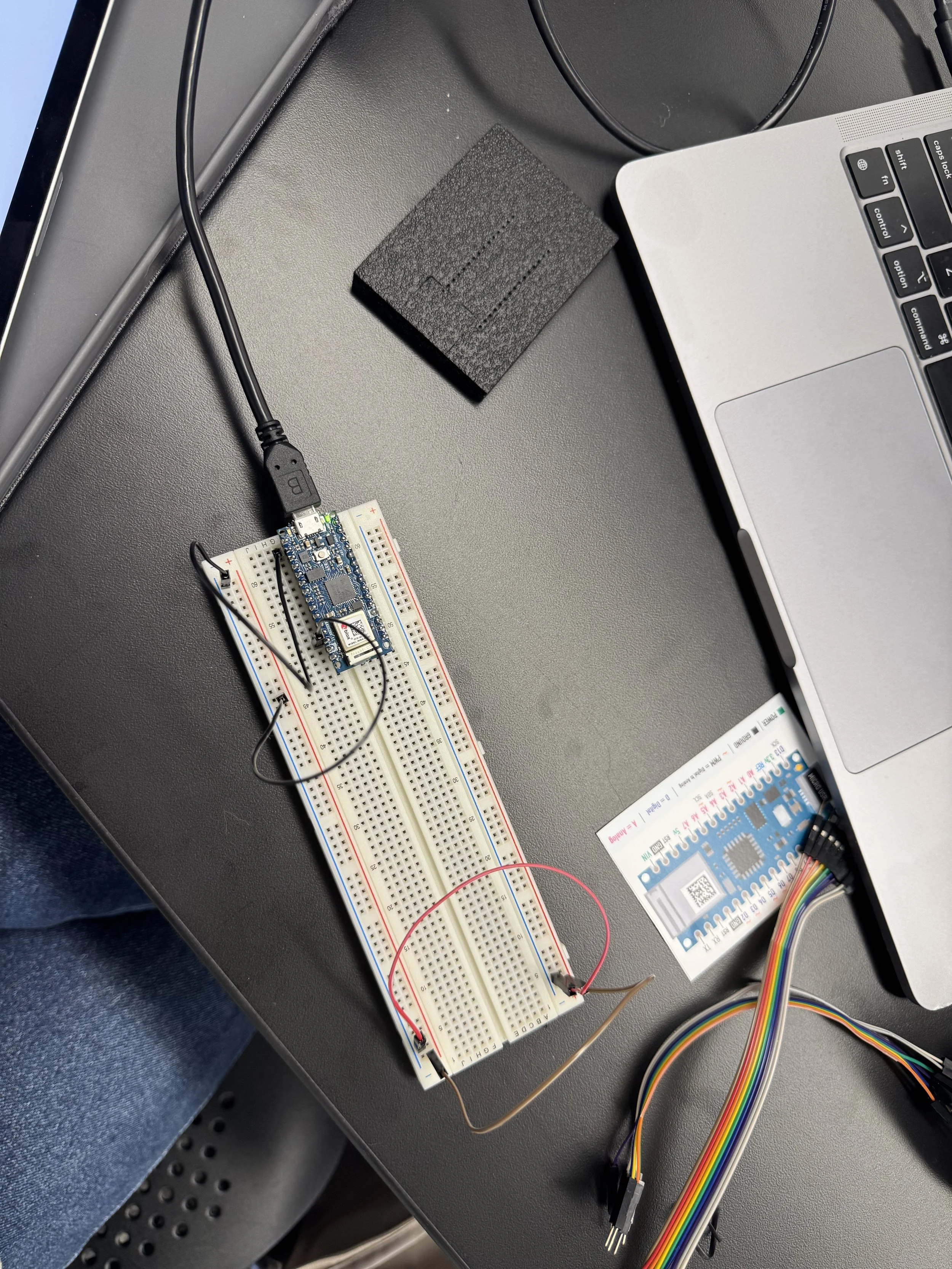
Before I even knew it, the class was over, and I had made my first circuit, where the Arduino Nano was connected to a breadboard. I learnt how to supply 3.3V from the Nano’s +3V3 pin (physical pin 2) and ground from one of the ground pins.


I learnt some of these things before in my physics class at UW-Madison. However, I realised I could read the circuit diagrams, but I couldn't conceptualise how they might look on the breadboard. It felt like I had lost so much memory, but I'm getting reconnected to it now, which was an interesting experience indeed.

The class concluded with a fun activity where we explored the 4th floor, searching for objects and learning about how they interact with people. I was paired with Lin, we went around the floor, and then we found this artwork. It wasn't easy to understand. There was a camera in front of us and a scanning option, which led to this website. And you stand there wondering what's happening, and the point of the artwork is to confuse you, to make you think about interactions that humans have with objects, that a camera being there implies you're being photographed.
Assignments
For the first lab, I wrote down the definitions to enhance my understanding, and then I used that knowledge to identify the components in the kit provided to us.


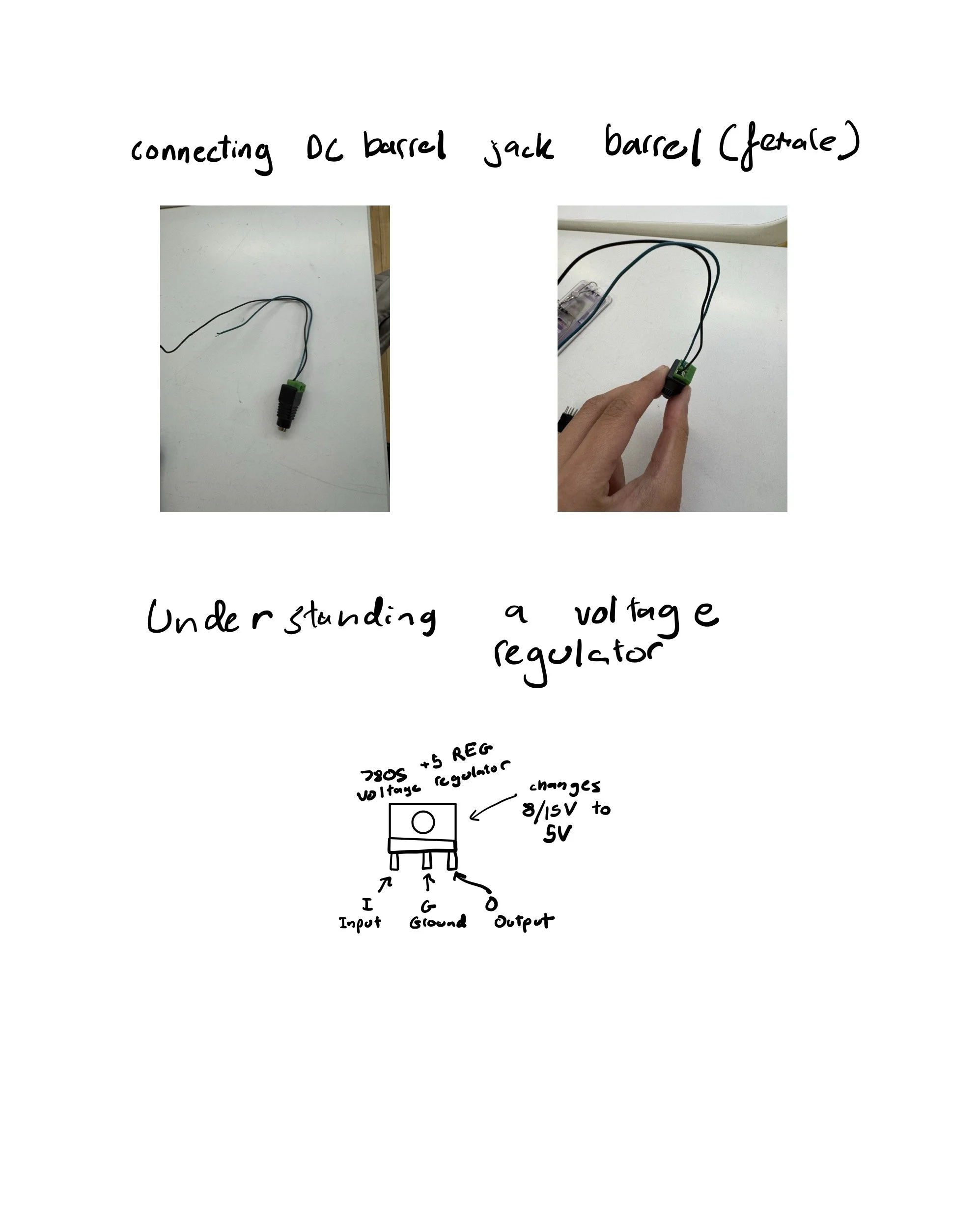
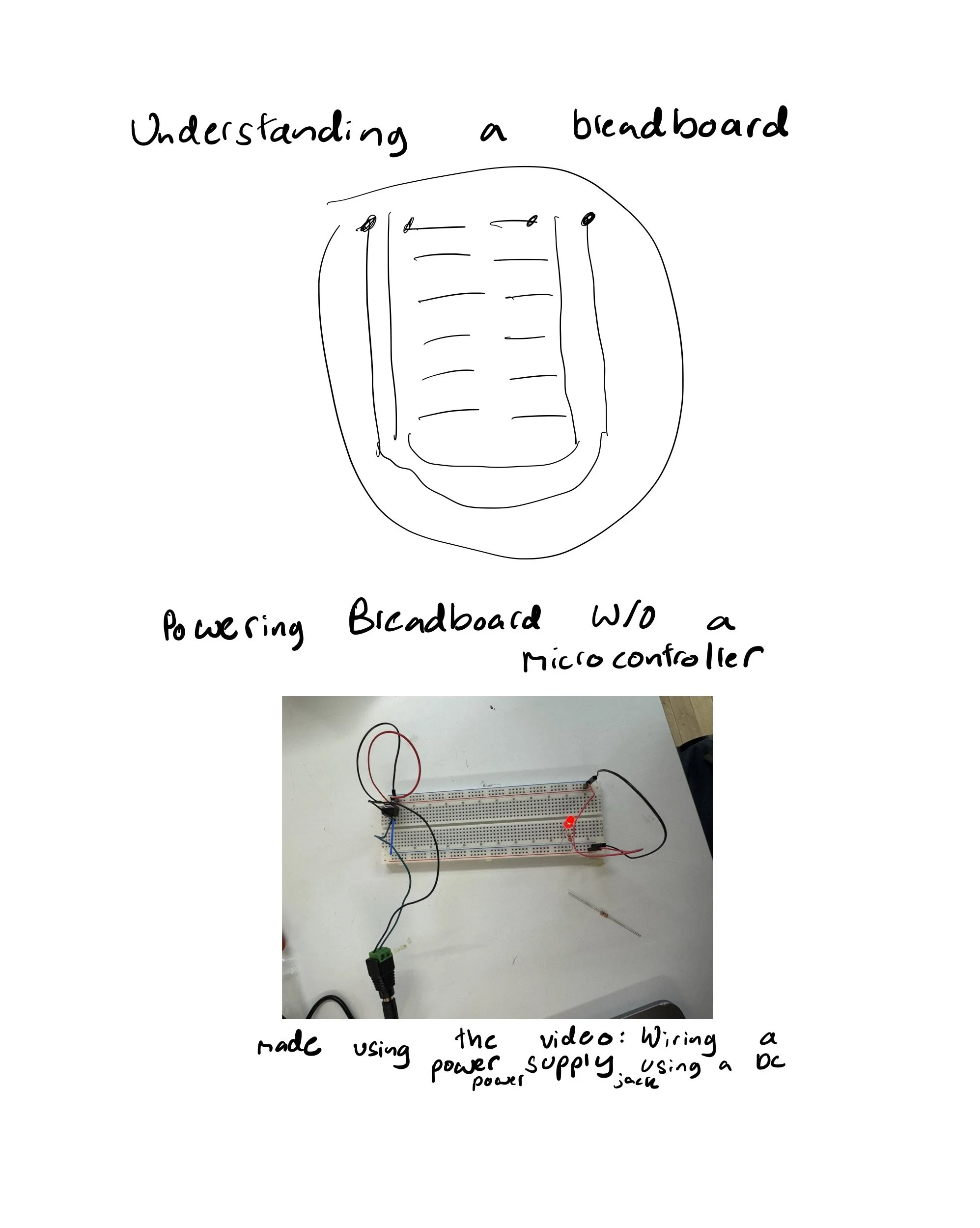
The second lab was another one that started becoming challenging, as I realised my concepts were not quite clear. Instead of connecting the Arduino to the breadboard, I decided to power the breadboard without a microcontroller. To do that, I referred to the video, but I got really confused since I didn't know how to set up a DC barrel jack. When I went to the shop, I saw that there are two kinds of DC barrel jack, where a "male" connector usually has a pin or pins "sticking out" and the "female" connector is designed to receive those pins. I found the naming method quite sexist, and then while talking to Cathy, she mentioned that they are going to change the official naming soon, which I thought was long overdue.
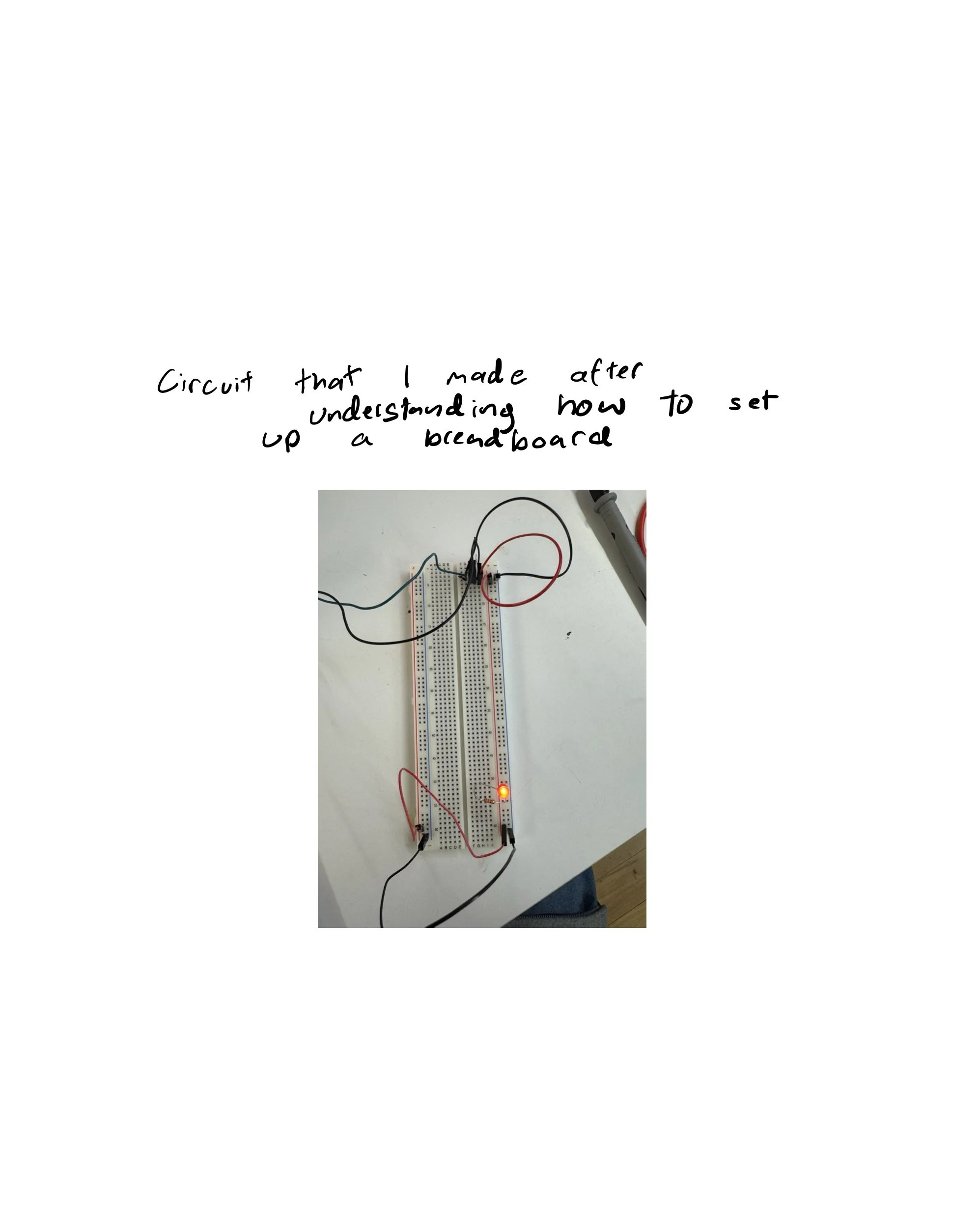
Tess showed me how to connect the DC barrel jack. So, I used the DC barrel jack (female) and borrowed a screwdriver. Used a wire stripper to cut wires and made a circuit. I was able to make a circuit, but when it came to answering the questions, I was struggling. Then Nujum taught me how a breadboard works and walked me through the questions and answers, which clarified my concepts more, and then I used the concepts at the end to make a circuit with different styles of connections that lights up a breadboard.
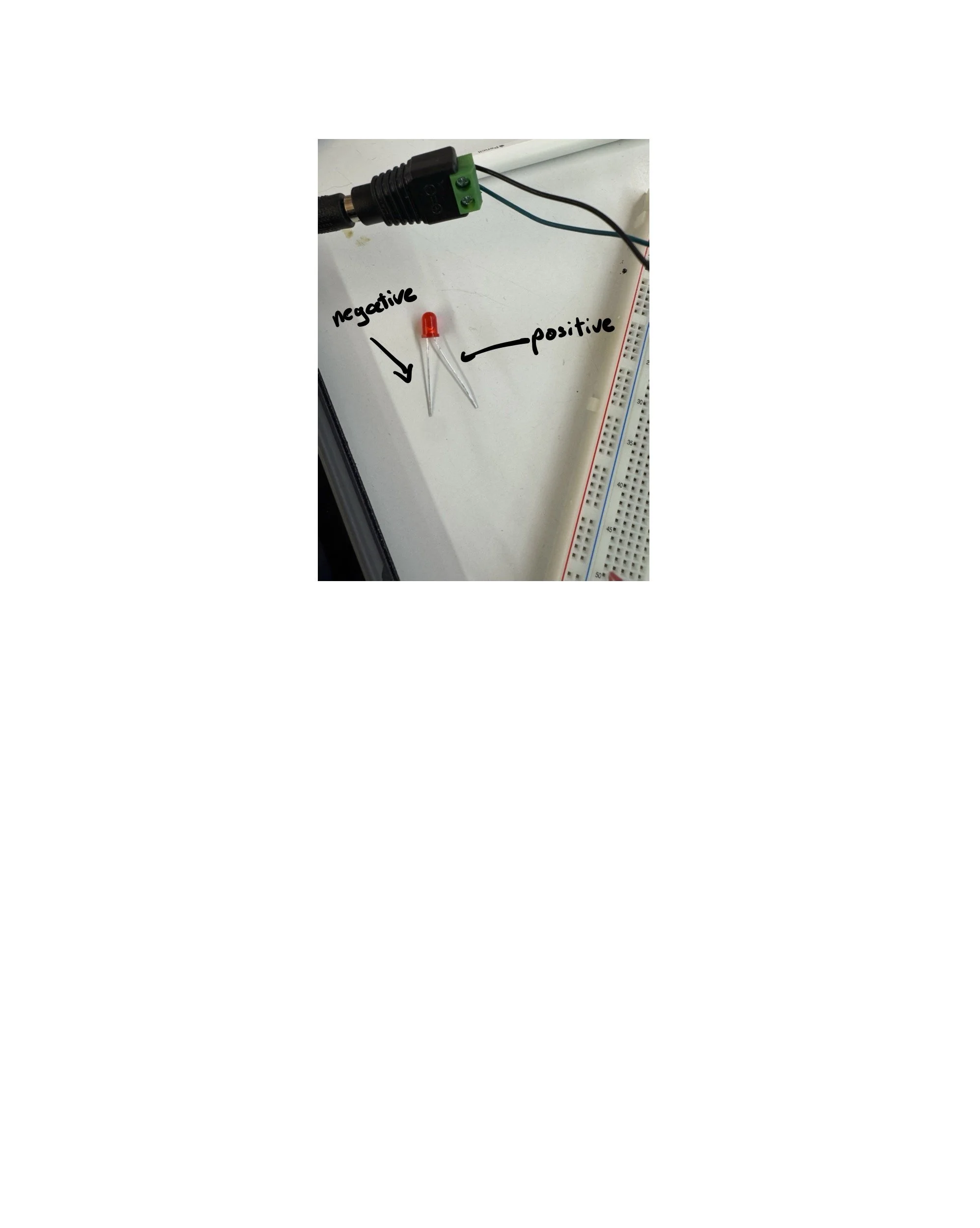
The third lab was straightforward after understanding how to work with a breadboard. I was initially unable to light the LED in parallel, so Cathy helped me set up according to the lab instructions, and my friend Esteban, who majored in biomedical engineering in undergrad and now studies at Game Center, helped me set up a new circuit with a potentiometer.


While using the multimeter, I ran into issues while doing a continuity check because I didn't have one of my wires connected to the voltage section. Then Nujum helped me correctly connect the multimeter. I was confused whether the diode checker setting is different from the multimeter setting, after class, because I asked a question about why my LEDs were lighting up. Tom told me that it was probably in the diode check setting, so maybe I wasn’t doing a continuity check, but I was doing a diode check. But, turns out most multimeters in ITP do not have a separate continuity check setting, it’s in the same section as the diode check.
For the last lab, I had a lot of fun because I was actually able to create a switch, and it challenged me to work on making a circuit of my own and test my understanding of the breadboard and circuits more clearly. I initially struggled because I was trying to set up a circuit in the manner in which a pushbutton switch works. Still, I wasn't entirely able to figure out how to set up the circuit in that manner, so I tried a simpler circuit, and made a switch by changing how the terminal strips of the breadboard were connecting to the power rails. I had a clip that I used to connect one wire with, and the other wire I put in a screw connected to a music box, so when I would touch the clip to the screw, the terminal strips were attached to the negative power rail, and that's how I designed my switch.
Moving forward within the lab, Project 1 is working on the circuit with three switches in parallel. Any one of the three will turn on the LED, which was one that I was able to do quickly.
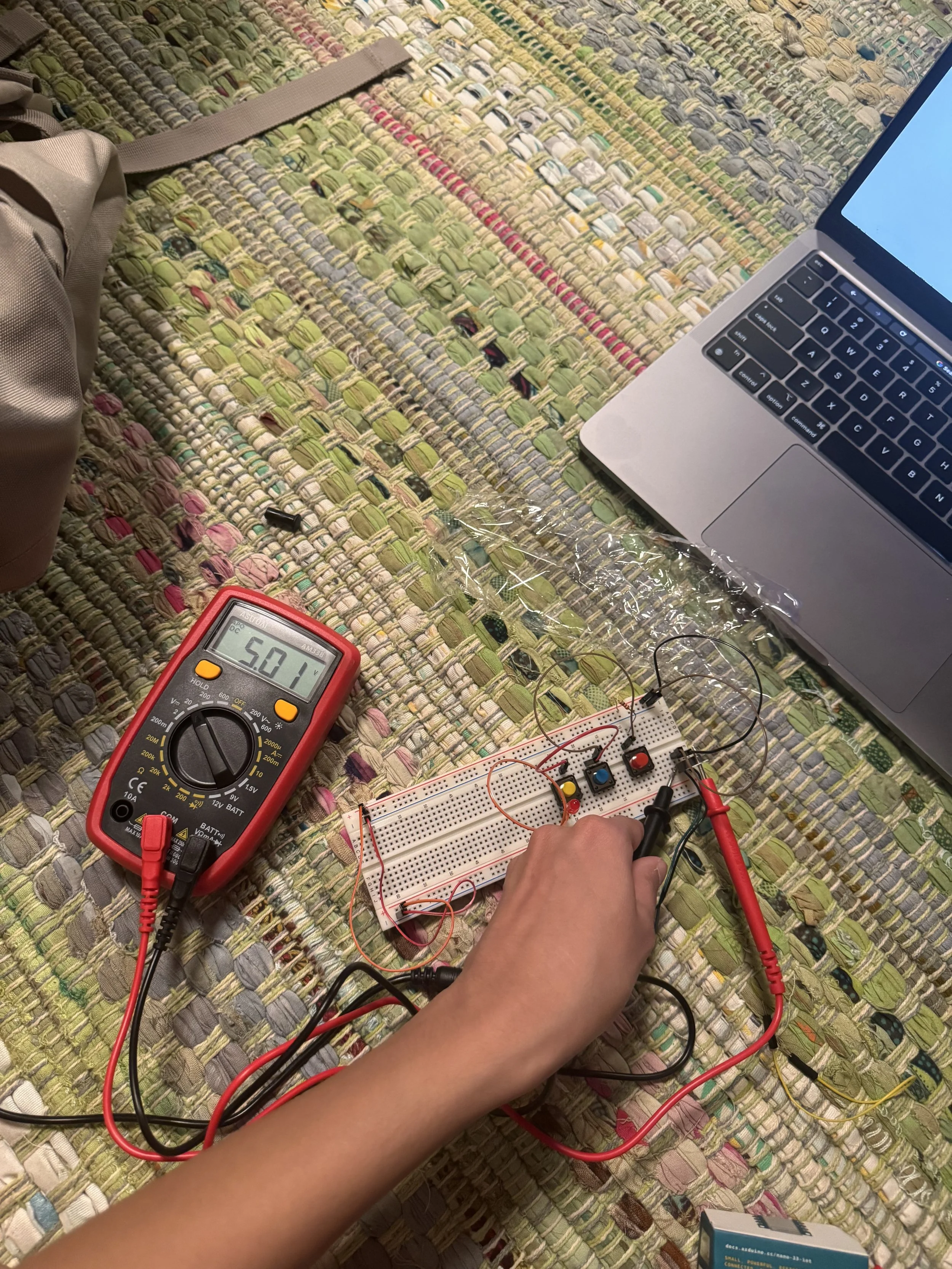
However, when I tried Project 2: Three switches in a series, the LED did not light up. But I checked using a multimeter, and electricity was flowing through.
Lastly, I wasn't able to work on Project 3 because I didn't have a motor.