
Week 2
In Class

In the class, I clarified a lot of my doubts. A few things that were really interesting and cleared my concepts really thoroughly were the water analogy to explain voltage, resistance, and current. I had a question about what transistors exactly do because I realised I was confusing them with transformers, and that also helped me understand it a lot better.
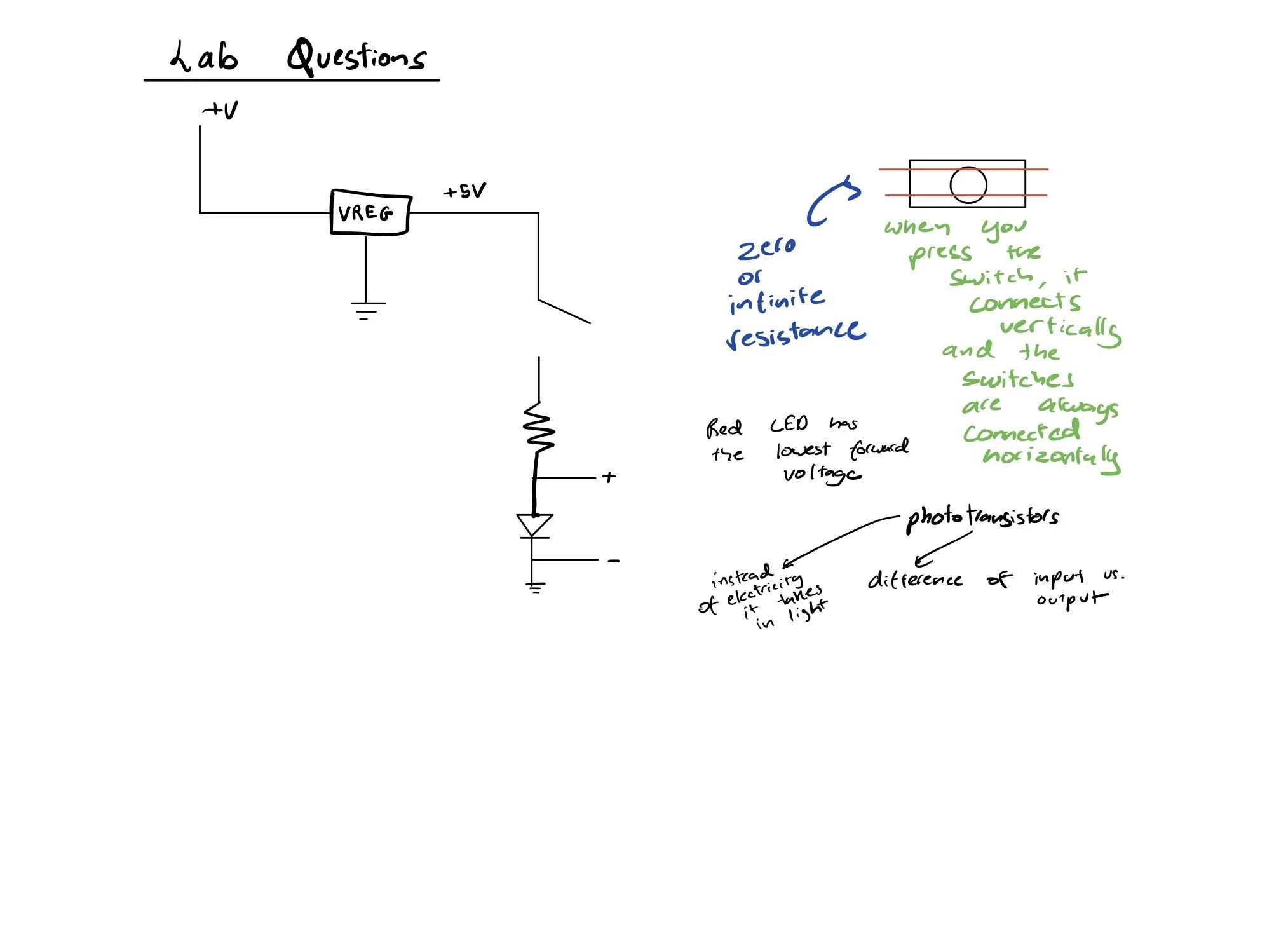
In terms of lab questions, essential things that were answered were that the red LED has the lowest forward voltage compared to other coloured LEDs. Also, the fact that different LEDs, even if they have the same. Then I was also able to understand resistance more clearly in switches. When a switch is turned on, there is zero resistance, whereas when it is turned off, it has infinite resistance. Furthermore, I was clearer about the way switches work. Then, during class, I also had a question about the difference between phototransistors and LEDs, and essentially, the difference between the two is that one works as though it takes in input (phototransistors) and the other outputs light (LEDs). In this case, instead of electricity, it takes in light. I also learnt that when you want to use a multimeter to measure current, you have to be in series to measure current.
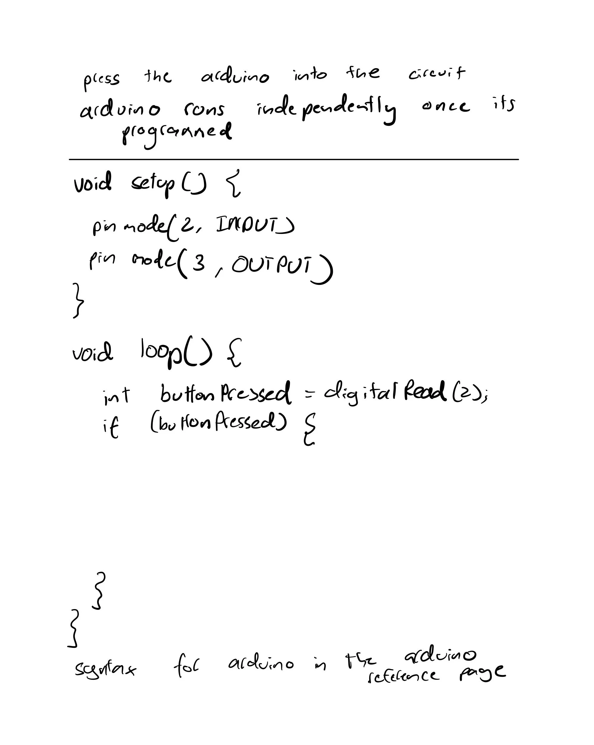
During class, we also went over coding in Arduino, and essentially, how an Arduino works as well. In C++ coding, the most important thing that I learnt has been:
// For digitalWrite(2, )
// The 2 is the pin at which the component is connected
// always unplug your board when you make changes

Furthermore, also learnt the difference between analog and digital.
Assignments
The first lab was Digital Input and Output with an Arduino. I redid the circuitry shown in Figure 13, which was easy to make because in the first class on physical computation, we learnt how to connect the Arduino and output +3.3V, so it was easy to communicate with a pushbutton.


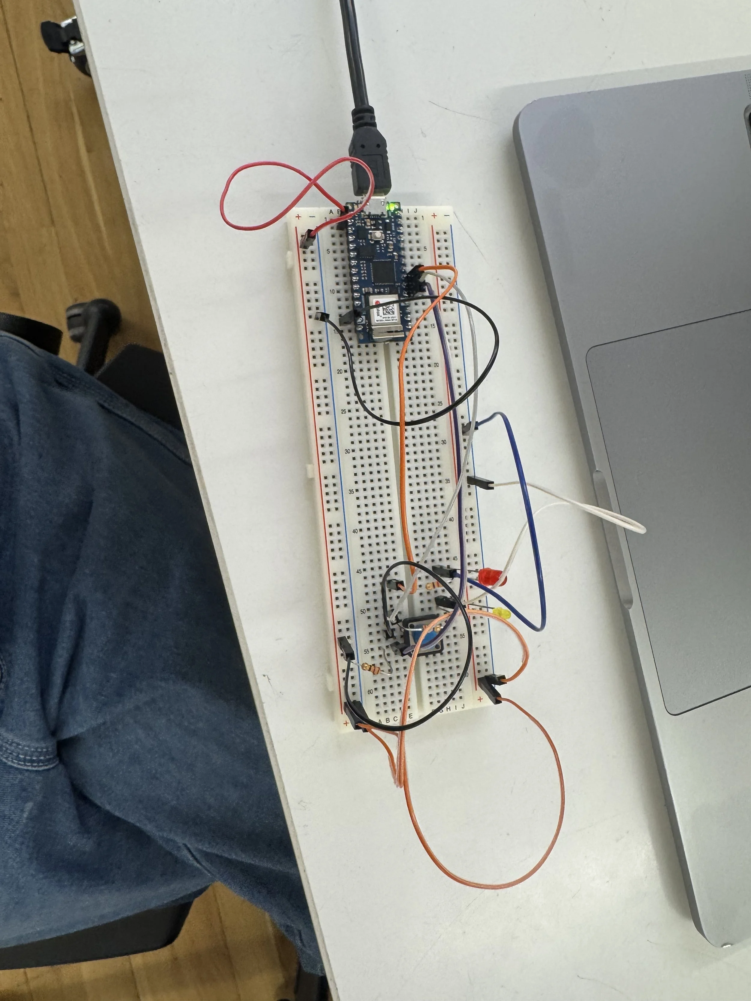
Then, I referenced Figure 16 to connect the Arduino Nano to the pushbutton and two LEDs. At first, I wasn't able to connect the circuit properly because my LEDs were initially busted, and then I kept placing the wires in the wrong breadboard pins, so I was confused as to how to troubleshoot it. I asked Arjun for help, and he told me that I wasn't supplying +3.3V to my circuit, which is why my LEDs weren't lighting up.


Then I programmed the Arduino as per the instructions to see how the LEDs changed. The program was based on the one provided in the lab, where it reads the digital input on pin 2. When the pushbutton is pressed, turn the yellow LED on and the red one off. When the pushbutton is released, turn the red LED on and the yellow LED off.
After that, I was playing around with the code, and I made this with reference to the Arduino forum, and while the code works interactively, the LOW and the HIGH readings were working oppositely.
// I reffered this webpage: https://forum.arduino.cc/t/counting-button-presses/119881/3

void setup() {
  // put your setup code here, to run once:
  pinMode(2, INPUT);    // set the pushbutton pin to be an input
  pinMode(3, OUTPUT);
  pinMode(4, OUTPUT);
}
int buttonPresses = 0;
int lastPressCount = 0;

void loop() {
  // read the pushbutton input:
  if (digitalRead(2) == HIGH)  {
    buttonPresses++;
  }
  if (lastPressCount != buttonPresses) {
    // if the pushbutton is closed:
    for (int n = 0; n <= 5; n++)    // lets blink
    {
      digitalWrite(3, HIGH);
      delay(500);
      digitalWrite(4, LOW);
      delay(500);
      digitalWrite(3, LOW);
      delay(500);
      digitalWrite(4, HIGH);
      delay(500);
      digitalWrite(4, LOW);
      buttonPresses++;
    }
    lastPressCount = buttonPresses;
  }
}
Then, for the lab, analog in with an Arduino, I followed Figure 17, and connected the Arduino Nano to a potentiometer and an LED. Which was relatively easy to follow, but I'm not sure why the potentiometer didn't quite dim as smoothly as I would have imagined it to do.
const int ledPin = 9;       // pin that the LED is attached to
int analogValue = 0;        // value read from the pot
int brightness = 0;         // PWM pin that the LED is on.
void setup() {
  // put your setup code here, to run once:
  // initialize serial communications at 9600 bps:
  Serial.begin(9600);
  // declare the led pin as an output:
  pinMode(ledPin, OUTPUT);
}

void loop() {
  // put your main code here, to run repeatedly:
  analogValue = analogRead(A0);    // read the pot value
  brightness = analogValue /4;       //divide by 4 to fit in a byte
  analogWrite(ledPin, brightness);   // PWM the LED with the brightness value
  Serial.println(brightness);
}


Then, at the end, I referred to Figure 23, and I was able to connect the breadboard as per the schematic; however, I again made the mistake of reading the Arduino pins, and I put the pin on 9 and 10 instead of 10 and 11. So, I spent a while trying to troubleshoot it, and then two people, Siddhi and another person whose name I couldn't recall, helped me figure that out in the circuit. I changed my code to become dimmer when I put pressure to see the difference more clearly, and changed the range values to match the values more clearly from my serial monitor.
const int redLED = 10;     // pin that the red LED is on
const int yellowLED = 11;   // pin that the yellow LED is on
int rightSensorValue = 0;  // value read from the right analog sensor
int leftSensorValue = 0;   // value read from the left analog sensor

void setup() {
  // put your setup code here, to run once:
  // initialize serial communications at 9600 bps:
  Serial.begin(9600);
  // declare the led pins as outputs:
  pinMode(redLED, OUTPUT);
  pinMode(yellowLED, OUTPUT);
}

void loop() {
  // put your main code here, to run repeatedly:
  rightSensorValue = analogRead(A0); // read the pot value
  // map the sensor value from the input range (400 - 900, for example)
  // to the output range (0-255). Change the values 400 and 900 below
  // to match the range your analog input gives:
  int brightness = map(rightSensorValue, 0, 1025, 255, 0);
  analogWrite(redLED, brightness);  // set the LED brightness with the result
  Serial.println(rightSensorValue);   // print the sensor value back to the serial monitor
  leftSensorValue = analogRead(A1); // read the pot value
  // map the sensor value to the brightness again. No need to
  // declare the variable again, since you did so above:
  brightness = map(leftSensorValue, 0, 1025, 255, 0);
  analogWrite(yellowLED, brightness);  // set the LED brightness with the result
  Serial.println(leftSensorValue);   // print the sensor value back to the serial
}